AC DC Power Supply
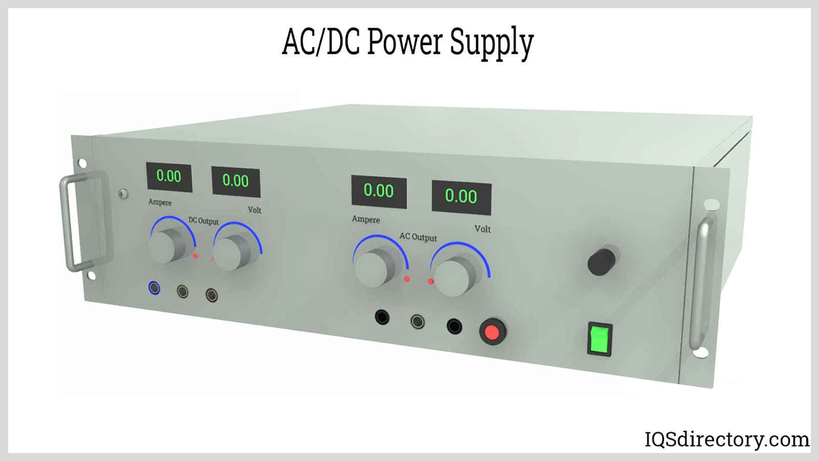
Power supplies are electrical circuits and devices that are designed to convert mains power or electricity from any electric source to specific values of voltage and current for the target device...
Please fill out the following form to submit a Request for Quote to any of the following companies listed on
A description of the types of electrical connectors with a list of recommended manufacturers
You will learn:
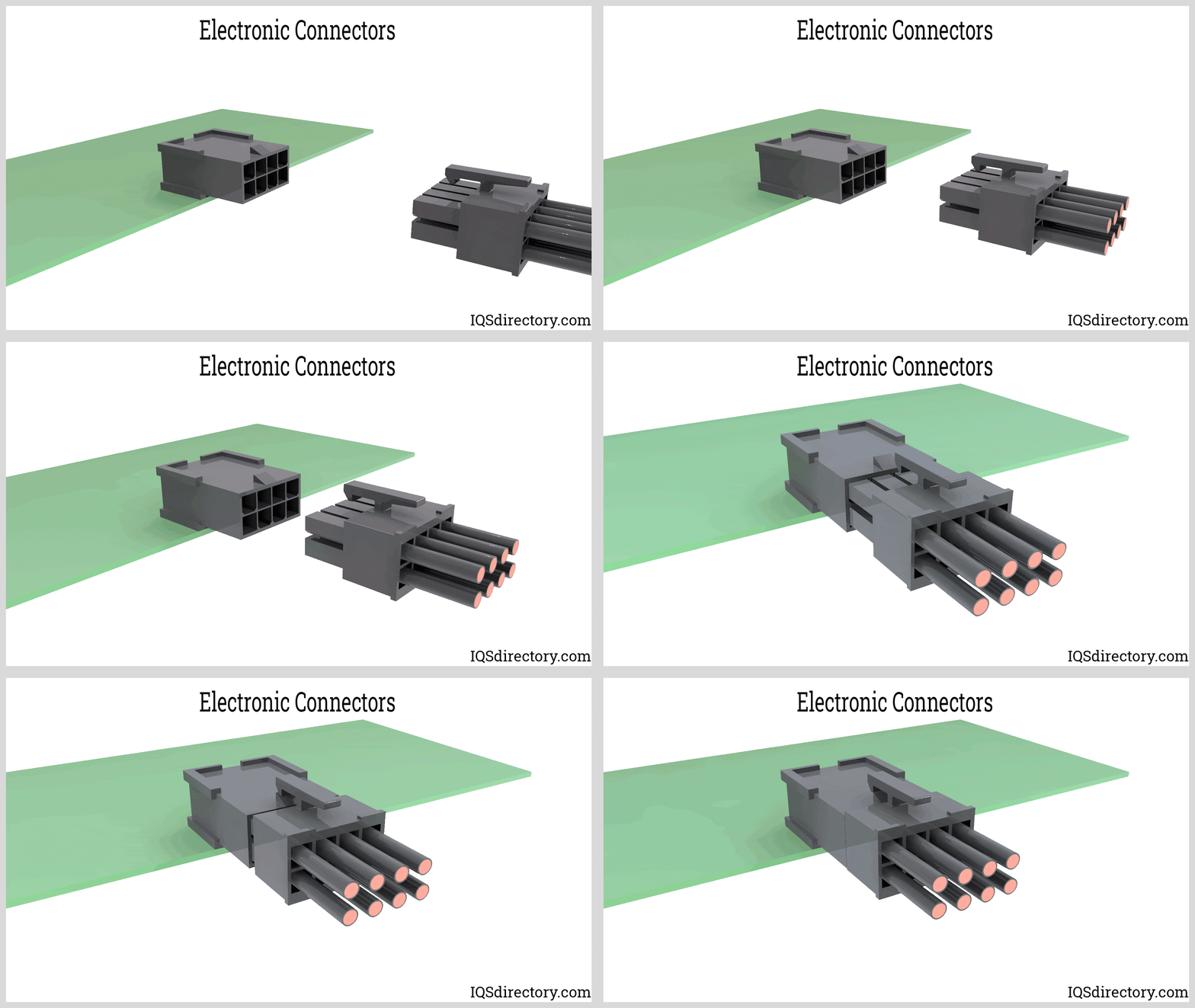
Electronic connectors are essential devices used to link electronic circuits. They play a crucial role in the assembly, installation, and power supply of electrical devices. These components are pivotal in a range of applications, including industrial equipment, consumer electronics, communication systems, and household appliances. Often underestimated, connectors are vital in ensuring that electronic products operate effectively. While some connectors are designed for permanent connections, the majority are intended to be temporary and easily detachable.
An electrical connector comprises two primary parts: the contacts and the housing, commonly known as plugs or receptacles. The housing secures the terminals, maintaining steady connections and providing insulation to prevent unwanted interactions with other electronic elements, thus avoiding short circuits. Plugs and receptacles shield the terminals from the environment and are typically constructed from insulating materials like molded plastics or ceramics.
Depending on the specific application, additional features may be incorporated into a connector. Keyed connectors are designed to fit in a singular orientation to prevent mismatched connections. Some connectors are equipped with locking mechanisms to avoid accidental disconnection. There are also connectors that are meticulously sealed to function efficiently in underwater conditions.
Connector terminals are the contact pins that create an uninterrupted pathway for electrical current to traverse between circuits. These are crafted from conductive materials, including brass, phosphor bronze, beryllium copper, and high-copper alloys.
The terminology used to describe the properties and characteristics of electronic connectors are:
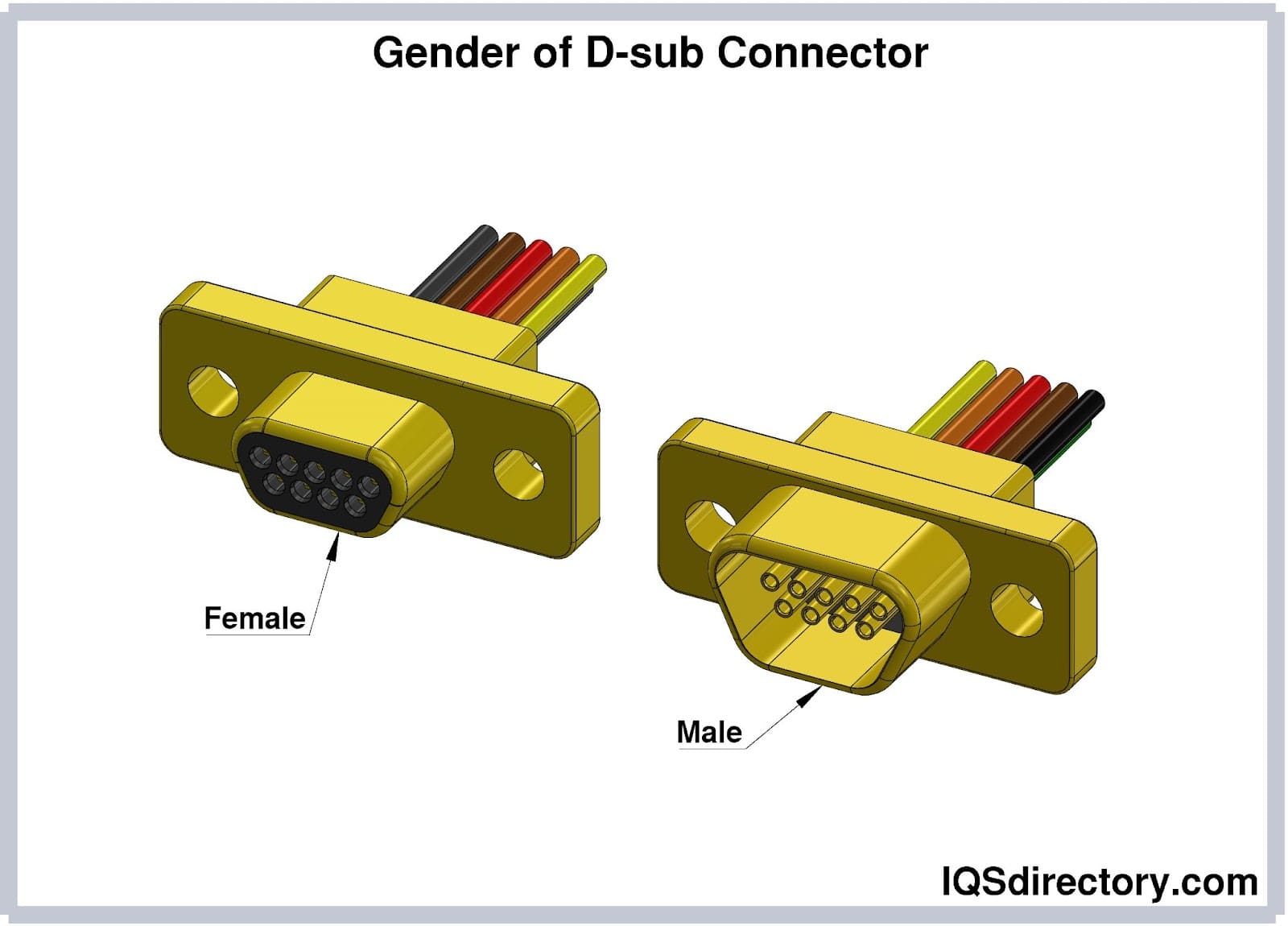
For electronic connectors, gender is used to differentiate the mating connectors that match together in size, shape, and number of pins. The plug or male connector has pins for connecting to the female connector, which has a receptacle, jack, or socket for the male pins. The female connector has socket holes that contain terminals to wires, cables, or devices. The pins of the male plug are inserted into the female jack or socket to make electrical connections.
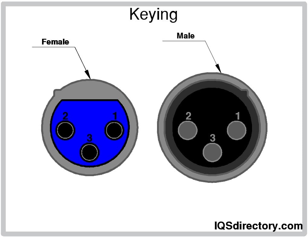
Most connectors plug in in one orientation. Keying is a unique form of electronic connector where more than one connector pair is required. A keyway prevents mechanical and electrical damage by making it physically impossible to mate pairs incorrectly. Connectors cannot be plugged if they have the wrong angle or the wrong socket. A keyway is for symmetrical connectors.
Locking mechanisms hold connectors in place when mated. They prevent connectors from being displaced when bumped or jolted, prevent accidental uncoupling, which can damage an electronic device. The various types of locking mechanisms include push-pull connectors, bayonet couplings, and fine thread screw couplings.
The number of contacts refers to the number of pins that will make an electrical connection. The number of contacts can vary from 2 to over 200, which is determined by the model and design of an electrical connector.
Contact pitch, or pitch, refers to the center-to-center distance between adjacent pins, measured in millimeters. When pins are arranged in an array, the pitch between rows and columns can be different. The contact pitch affects the compatibility of connectors.
A larger pitch means fewer terminals per connector area, which reduces electrical arcing. When electrical current jumps between pins, it is referred to as electrical arcing if the pins are too close to each other. Contact pitch is carefully calculated during electrical connector assembly.

Pin numbering is a method used to identify each of the pins of an electronic connector. The counting system is from left to right or bottom to top, which is determined by the type of connector. Pin numbering makes it possible to have precise wire connections when working with multiple pin connectors.
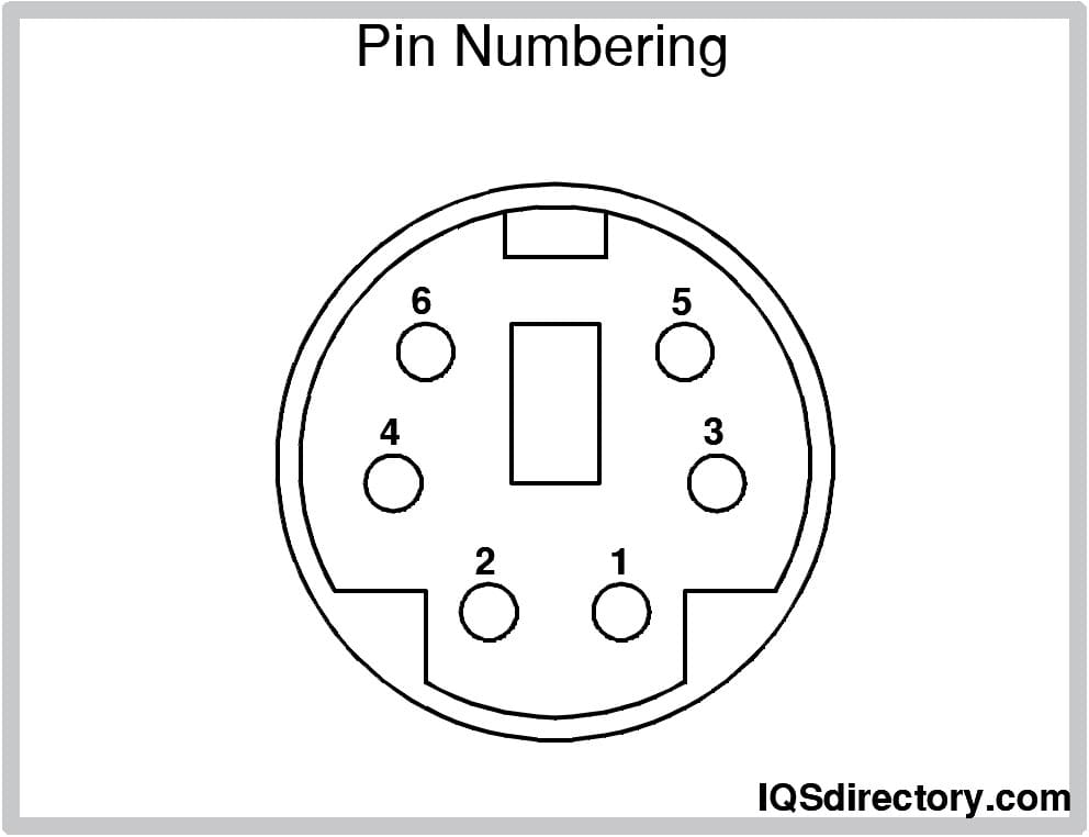
The pin sequence of an electronic connector determines which pins make contact first when connected. The order of the pin sequence ensures proper functionality and protects devices by having ground pins make contact first. The purpose of pin sequence is to prioritize the order in which pins make connections.
Mating cycles are the number of times an electronic connector can be connected and disconnected. USB connectors can be mated thousands of times, while FFC and FPC connectors have far fewer cycles. The factors affecting the mating cycle are connector materials, plating type, thickness of pins, pass/fail threshold, and mating style.
Mounting is how an electronic connector is mounted to an electrical device. The mounting types are board, through-hole, surface, edge, panel, and cable. The method of mounting determines how a connector can be placed on a device.
The termination of an electronic connector is how the conductive wires are attached to the connector. Wires are stripped and attached to the connector’s contact points by being crimped, soldered, or screwed on.
Strain relief is a fitting or bushing that dissipates forces acting on an electronic connector to prevent stress and damage and make an electronic connector mechanically stable.

The performance parameters of an electronic connector are a list of its functions in regard to environmental factors. The list includes current rating, voltage rating, operating temperature range, contact resistance, insulation resistance, environmental sealing, and mating force.
Some electronic connectors have features for special applications and include:
Electronic connectors are categorized based on the level of interconnection:
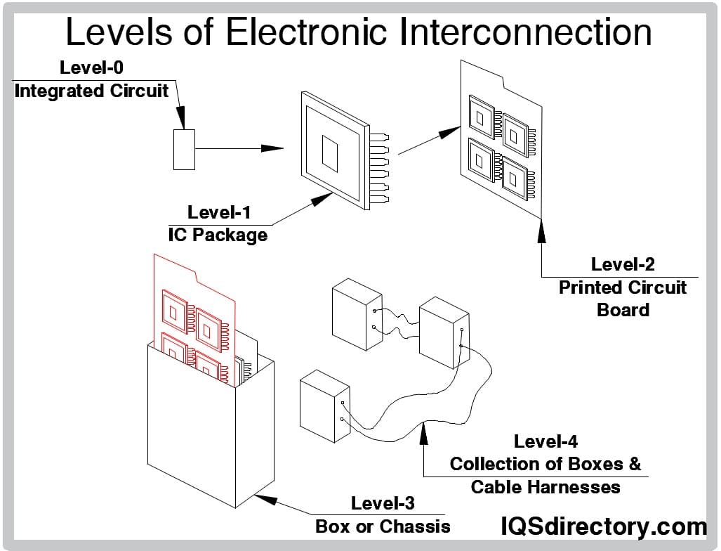
The world of electronics is ever growing and depends on electronic connectors to establish connections between various components. The use of electronic connectors has led to the development of a wide range of sizes, types, and distinctive electronic connectors that provide seamless connectivity.
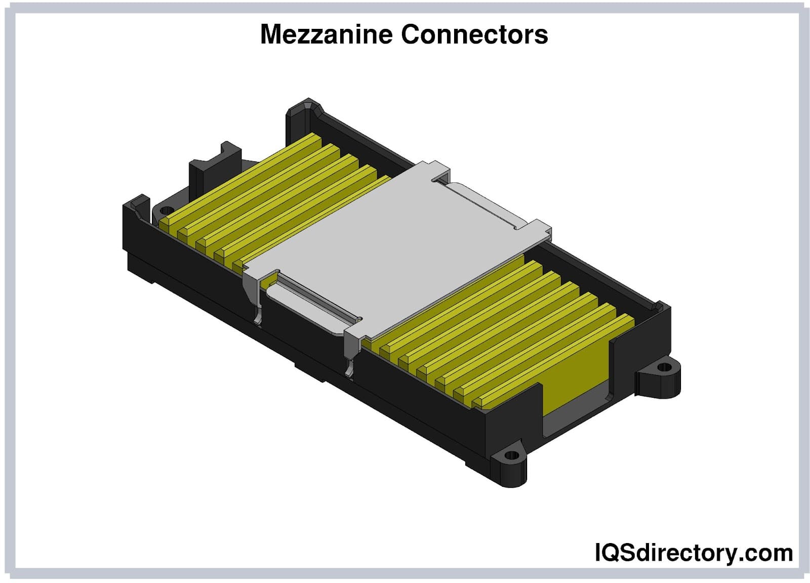
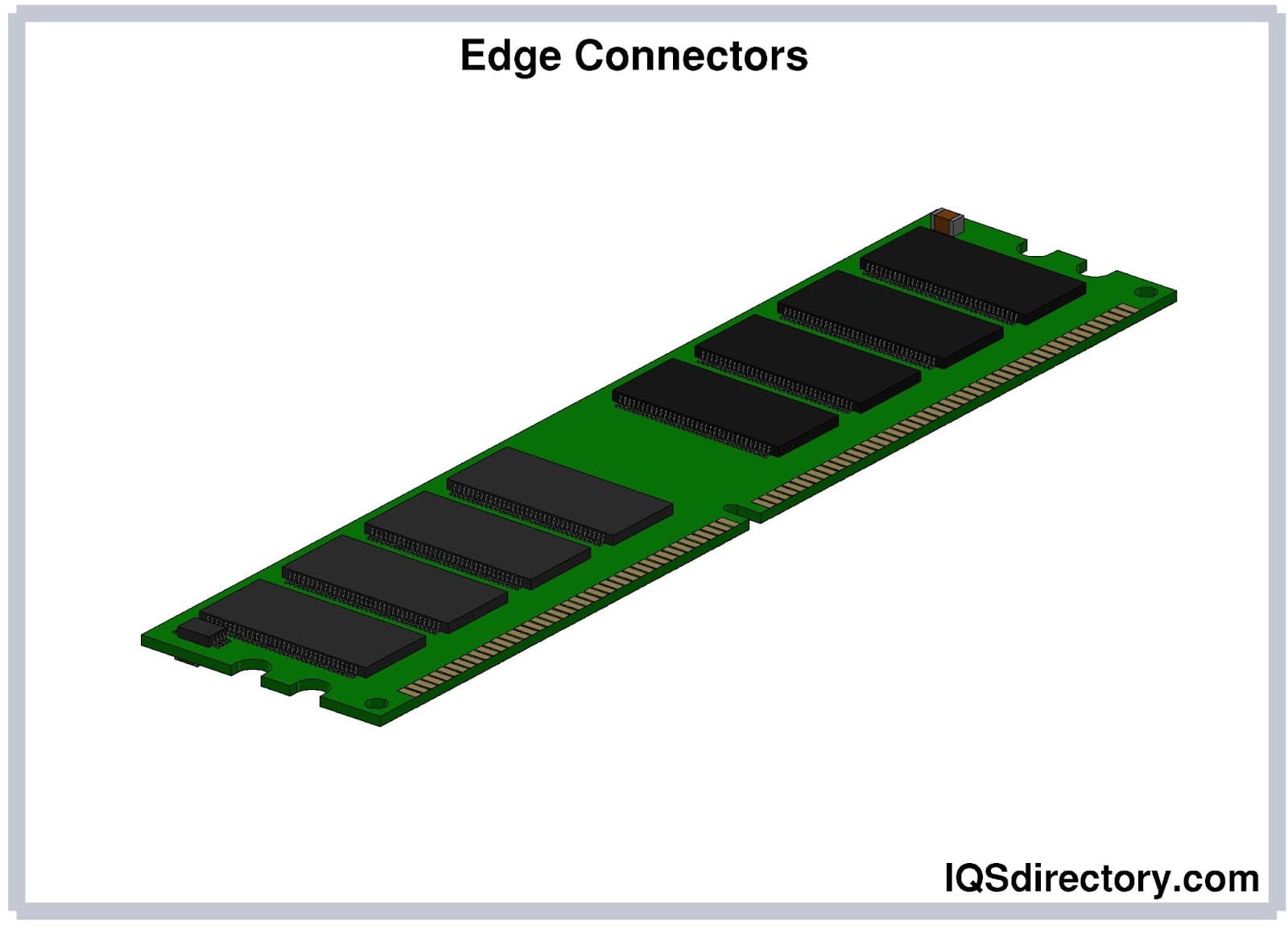
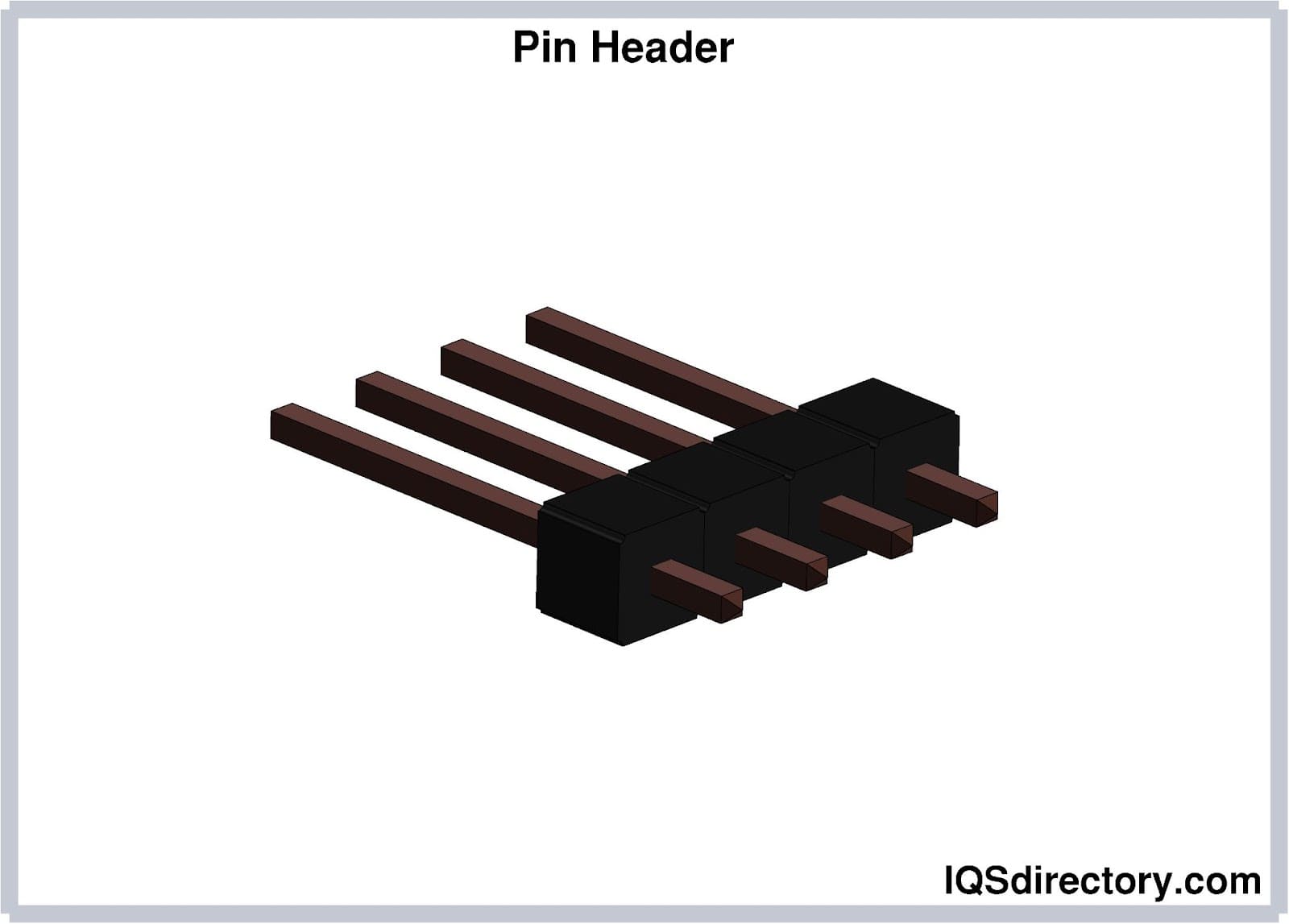
Board-to-board connectors are a group of connectors that join printed circuit boards (PCB) without using a cable. They consist of a plug and socket and are included PCBs by vias, which are through-hole, or surface mounts. The connections for PCBs can be perpendicular or parallel with mezzanine connector PCBs being a stacking configuration, while edge connectors mate on the edges of single-sided or double-sided PCBs.
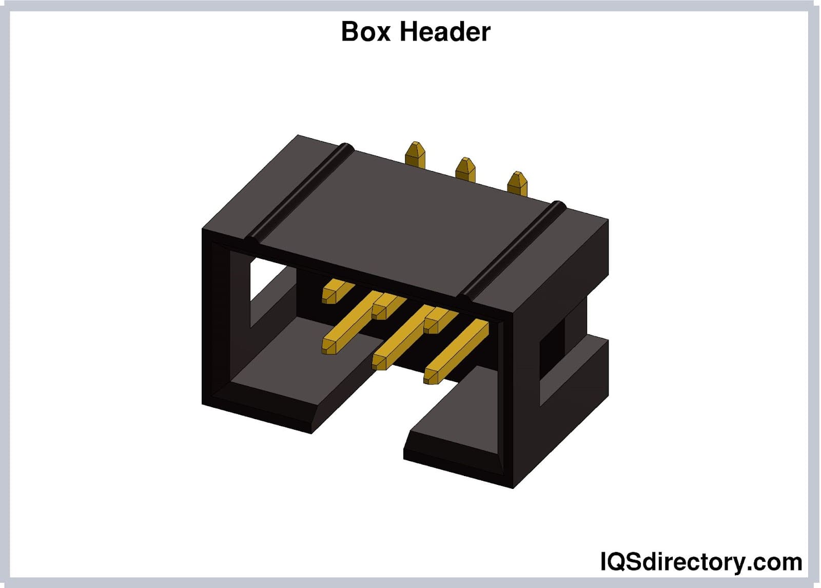
Box header connectors or shrouded header connectors are a form of board-to-board connector that have exposed pins with a plastic guide box. The design of box header connectors makes mating easier. They come with keying to prevent mismating and can have a notch cut out of the box to ensure correct mating.
A backplane functions as a central framework that interconnects multiple PCBs, aligning the pins of one board with corresponding pins on other boards. They are commonly used in computers and telecommunications equipment for data exchange between components. The name for backplane connectors comes from their use with mainframe computers where they were located at the back of the mainframe’s casing. In modern computers, they are part of top of rack switch applications and hybrid hard drive (HHD) clusters.

Power connectors are connectors that allow electrical current to pass through them to provide power to a device. They carry either a direct current (DC) or an alternating current (AC).
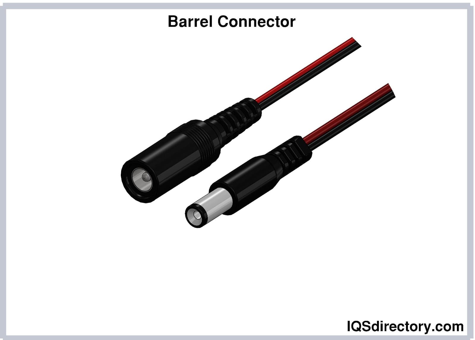
Barrel connectors, also known as coaxial power connectors, connect electronic devices to an external power source. Low voltage DC from a wall-mounted adaptor is transmitted to the electronic device through a barrel connector. They are widely used in consumer electronics and are available in standard diameters and lengths.
The barrel plug is composed of concentric metal cylinders separated by an insulating layer. The inner cylinder contains the pin of the barrel jack. The various methods for mounting the barrel jack are on a PCB, panel, or cable. Inside the jack, a cantilevered spring presses against the outer sleeve of the plug, ensuring that the inner sleeve makes contact with the pin.
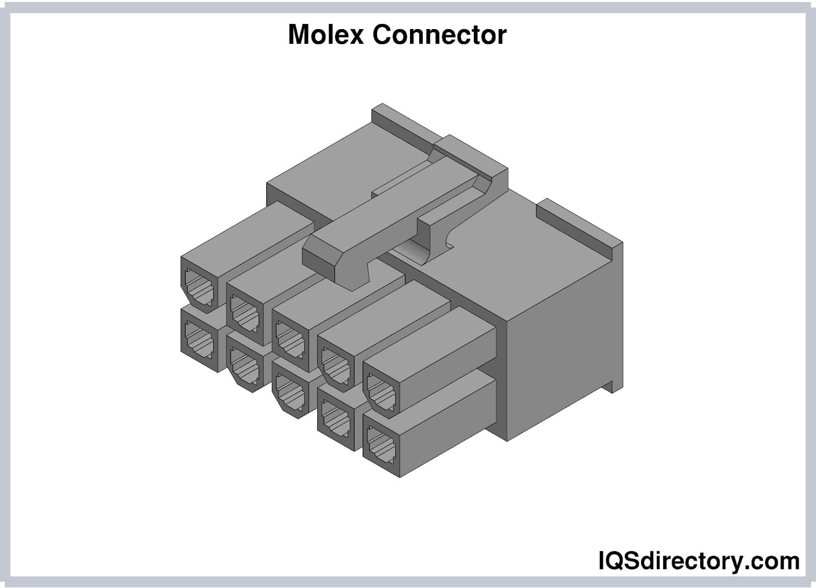
Invented and patented by the Molex Connector Company in the late 1950s, Molex connectors are used for powering computer drives and other devices. Molex connectors consist of cylindrical spring metal pins that connect with matching cylindrical spring metal sockets. With keyed configurations for correct alignment, Molex connectors can have between 2 and 24 contacts with pins and sockets secured in a plastic housing.
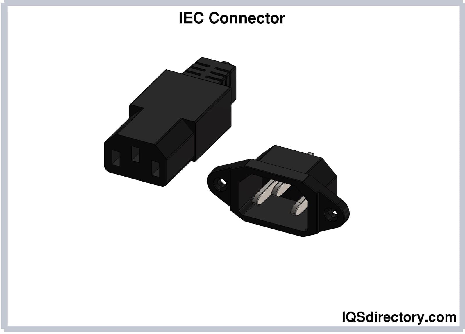
IEC connectors are connectors that meet the standards stipulated in IEC 60320. The content of IEC standard 60320 specifies the components for connecting power supply cords to electrical equipment with a voltage rating of 250 V and a current rating of 16 A. IEC connectors vary in accordance with their current rating, temperature rating, dimensions, and number of terminals.
The components of IEC connectors include an outlet power end or male component and an inlet female component. IEC components are identified by the prefix “C” followed by a number with the number of the inlet or female being one higher than that of the outlet or male component. The C13 connector is matched with the C14 inlet, which have three conductors, a current rating of 10 A, and a maximum temperature rating of 700°C.
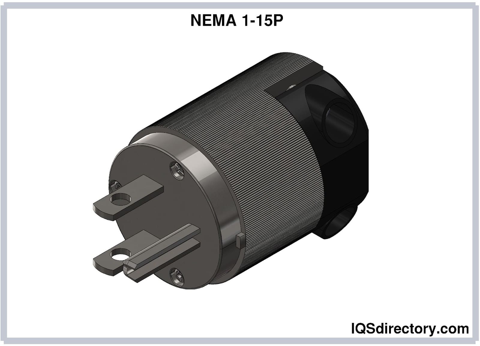
A NEMA connector is a category of power plugs and female receptacles that are compliant with the standards of the National Electrical Manufacturers Association (NEMA). Although NEMA standards are common in North America, they are also used internationally by a few countries.
The distinguishing feature of NEMA connectors is the coding system that uses a set of numbers and letters to describe a connector’s characteristics. The initial code identifies the locking mechanism. Connectors beginning with the letter “L” have a twist-lock feature. If there’s no letter, it is a non-locking connector. The second part of the code, a number before the hyphen, specifies the NEMA type, which denotes the number of poles or current-carrying terminals, wire connections, voltage rating, and other identifying features. The number after the hyphen is a connector’s current rating in amperes. The final letter of the code is a “P” for plug and “R” for female receptacle.
Non-locking NEMA connectors have straight blades on their plugs, making them easy to connect and disconnect from their female receptacles. In contrast, twist-locking NEMA connectors use curved blades that can be rotated and locked into place, preventing accidental disconnection. Twist-locking connectors are suited for industrial and commercial settings where secure tight connections are a necessity.
RF connectors are designed to work with radio frequencies in the multi-megahertz range. They maintain shielding for coaxial cables, which has earned RF connectors the name of RF coaxial connectors. RF connectors help establish electrical connections for radio frequency transmission systems. The structure of a RF connector includes a center conductor, outer conductor, and insulation to maintain shielding for the coaxial cable.
As with many connectors, RF connectors have female and male versions. In many instances, RF connectors are used for applications unrelated to radio frequencies due to their protective shielding. Fastening and spring mechanisms are included with RF connectors to reduce insertion forces.

A terminal block is a modular, insulated device designed to connect or terminate multiple wires. It has a series of terminals aligned in a strip with each terminal linked to a metal strip inside the block. The metal strip allows for electrical conduction between the connected terminals, while a clamping mechanism holds the wires in place. Terminal blocks can be oriented horizontally, vertically, or at a 45-degree angle, and can be mounted on panels or DIN rails.
Their Structure
Their Application
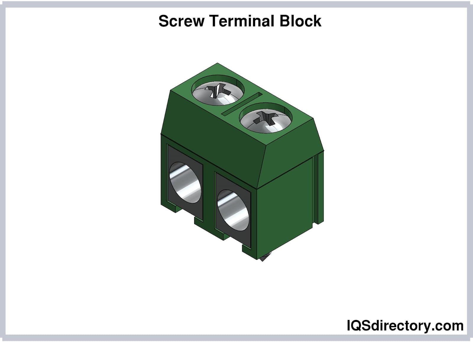
Screw terminal blocks press the wire and the strip together and are the most common type of terminal block due to their ability to accommodate a wide range of wire sizes. A ferrule, Latin for small bracelet, is a metal tube that is placed over stranded wire to secure the strands for a screw terminal. They are narrow metal circular rings that reinforce, secure, and bind together strands.
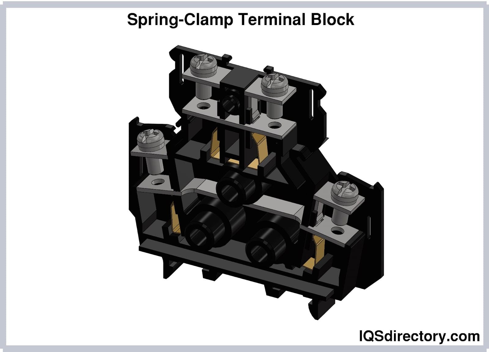
Spring-clamp terminal blocks are suitable for clamping smaller wires and are used to attach wires to the strip. The three forms of terminal blocks are single pass through, dual level, and three level. Spring-clamp terminal blocks are capable of handling multiple wires due to their very secure clamping mechanism.
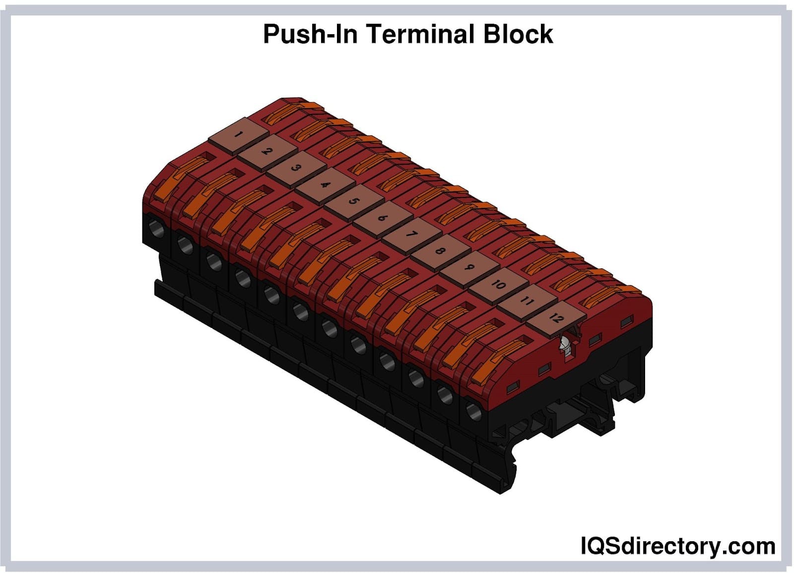
Push-in terminal blocks or quick disconnect terminal blocks can be male or female. Male push-in terminal blocks include tabs that provide connection with female terminals. The female version has holes to accept male tabs. There are several types of push-in terminal blocks making it possible to adjust them to fit any application.
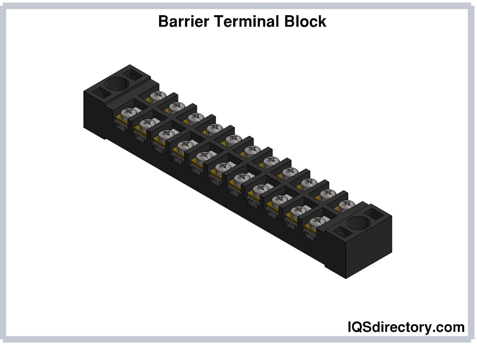
Barrier terminal blocks have a plastic or metal housing that make it possible to connect several wires or conductors to a circuit. The design of barrier terminal blocks includes a pressure plate or set of screws for clamping wires in place. Barrier terminal blocks are widely used for their versatility and ability to be installed, dismantled, and reconnected.
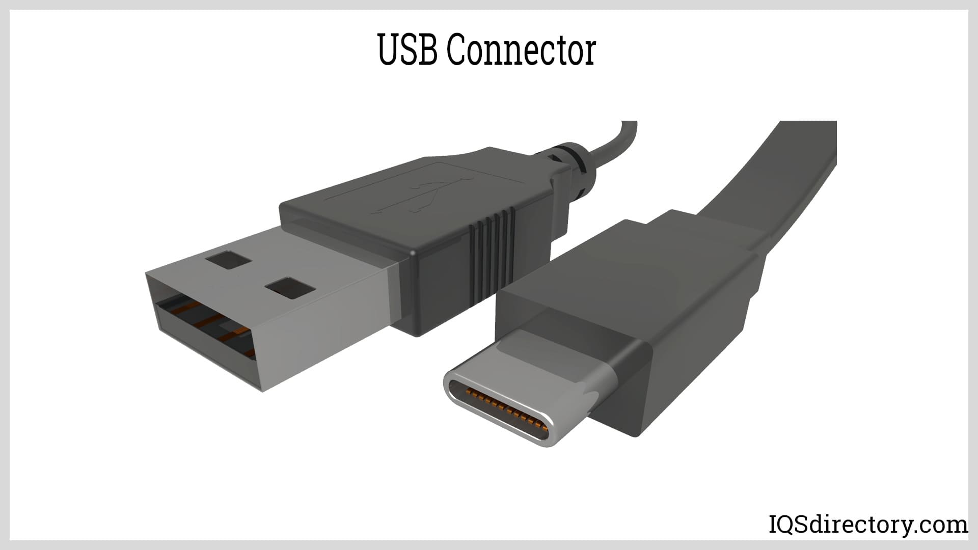
A USB is an interface used for data transfer and power supply. They are found in smartphones, computers, and consumer electronics. USB connectors have a male component that plugs into a female port and have four or more shielded contacts enclosed in a plastic housing with a molded strain relief. Except for USB-C, USB connectors have an asymmetrical design that serves as a keying mechanism to ensure proper alignment.
The versions of USBs include USB 1.0, USB 1.1, USB 2.0, USB 3.0, USB 3.1, and USB 3.2. Newer versions offer faster data transfer speeds but are backward compatible with older versions.
USB connectors are categorized by their receptacles and sizes. USB-A and USB-B have male and female versions while USB Minis are divided into Mini-A, Mini-B, and Mini-AB. USB Micros are compartmentalized into Micro-A, Micro-B, and Micro-AB with USB-C being a version onto itself.
USB-A female connectors are commonly used as host ports in computers, hubs, or devices. They allow for peripherals to be connected. USB-A female extension cables have a female A connector on one end and a male A connector on the other end.
USB-A male connectors are found in keyboards and mice attached to built-in cables. They are used on USB memory sticks and designed for board mounting.
USB-B female connectors are larger. They are used in applications where size is less critical. USB-B female connectors are known for their reliability and are used in removable and via or through-hole board mount applications.
USB-B male connectors are at the end of cables. Their affordability is the reason for their widespread use.
USB Mini female connectors were used on older MP3 players, cell phones, and external hard drives as surface mount connectors. They have been replaced by USB Micro connectors.
USB Micro connectors are smaller than their predecessors and include a fifth pin for low-speed signaling, making them suitable for USB-OTG (On-The-Go) applications.
Audio and video connectors are a diverse category of electronic connectors designed to transmit audio and video signals. They can handle analog and digital signals using male (plug) components and female (jack) components.
Audio connectors support monophonic (single audio channel) or stereophonic (multiple audio channels) signal systems.
Phone Connectors have coaxial contacts that include a tip (T), ring (R), and sleeve (S). They are used in combination with 3 to 5 contacts and are found in phones, headphones, speakers, and other audio devices.

DIN Connectors were originally standardized by the Deutsches Institut für Normung (DIN) and are used for transmitting analog audio signals. They have three or more metal pins arranged in a conductive ring and include a notch in both the male and female components to ensure proper alignment. Mini-DIN connectors are smaller versions of standard DIN connectors.

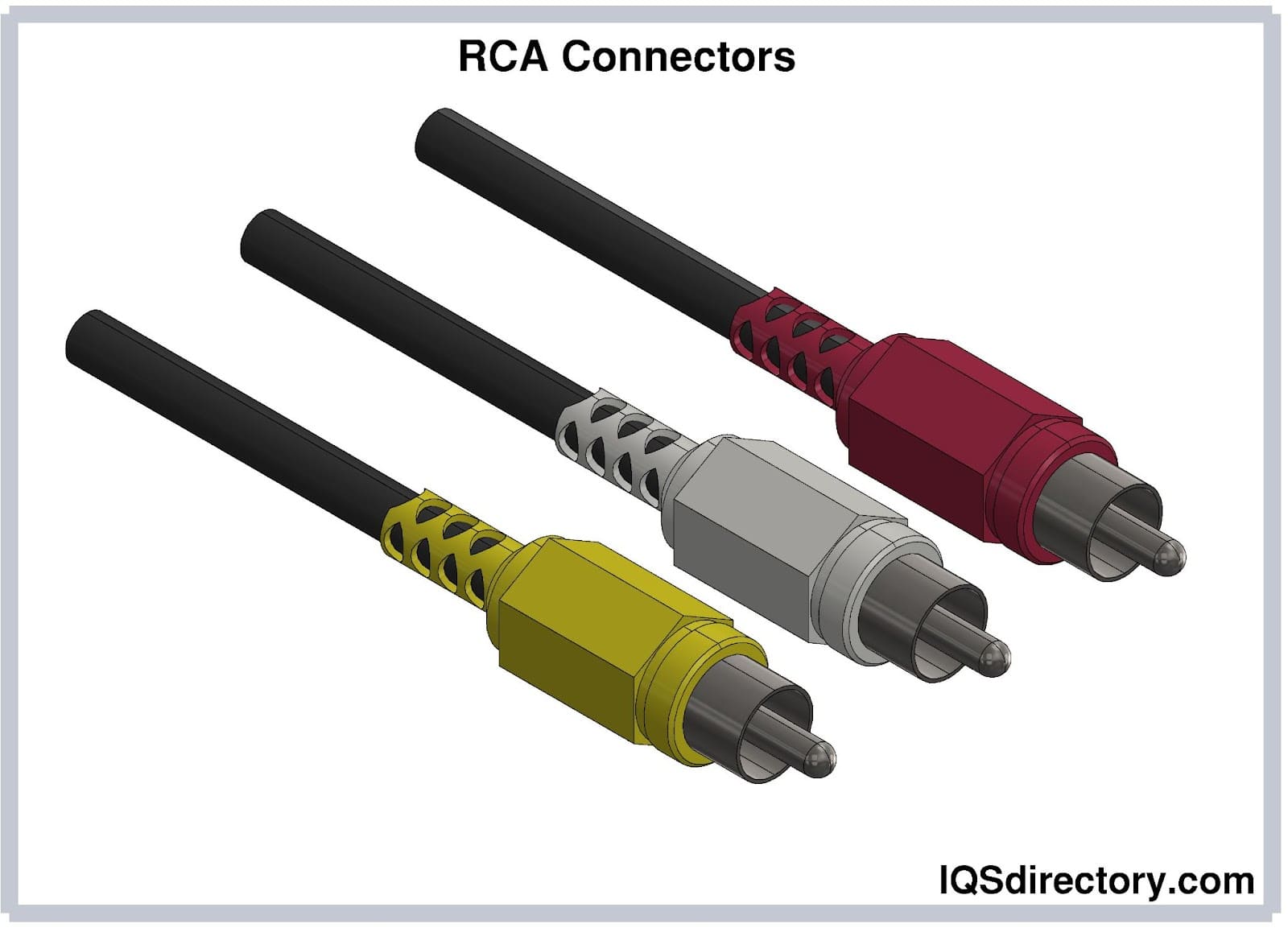
RCA Connectors are used for transmitting stereo audio and video signals with an outer conductor and central pin as an inner conductor. They are color-coded with yellow for composite video and red and white for audio stereo.
XLR Connectors are circular connectors with three to seven pins and a notch that acts as a keying mechanism to ensure proper connection. They are commonly used for professional audio and video applications. The XLR stands for “External Line Return”. The balanced wiring of XLR connectors cancels out interference and enables XLR connectors to carry 48 V phantom power.
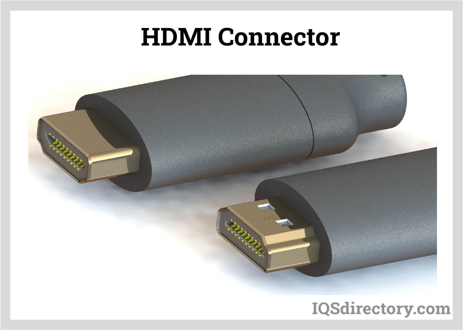
High-Definition Multimedia Interface (HDMI) Connectors are used in modern home entertainment devices, projectors, computer monitors, and digital audio devices. HDMI connectors help transition minimized differential signaling (TMDS) technology to large amounts of digital data. Standard types of HDMI connectors include the standard (type A), dual-link (type B), mini (type C), micro (type D), and Automotive Connection System (type E) HDMI connectors.
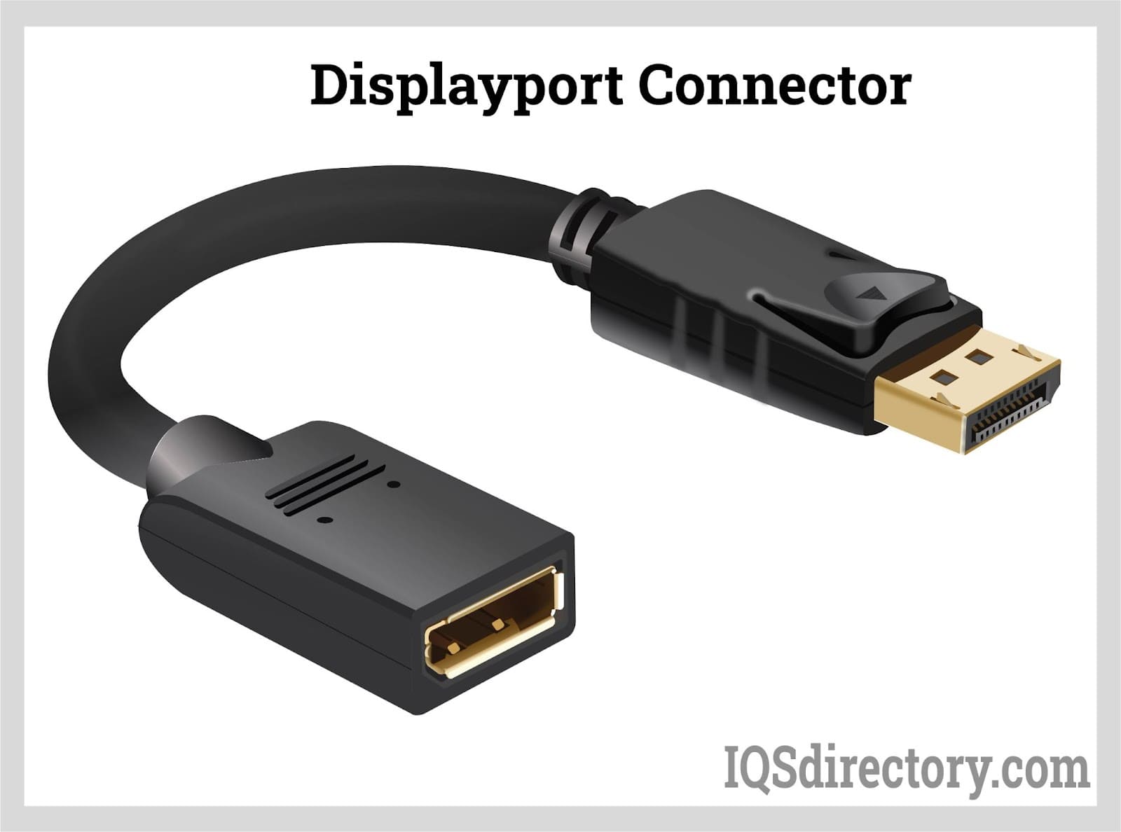
DisplayPort (DP) Connectors link audio and video sources to displays, like monitors, TVs or projectors, are used for high-definition graphic displays, and computer systems. DisplayPort connectors are available in different versions, which are designed to transmit video and audio signals through a single cable. They have 20 or more pins and come in varying lengths.
Digital Visual Interface (DVI) Connectors are able to support analog and digital video signals over a single cable. Unlike HDMI connectors, DVI connectors can only transmit video signals. They were introduced as a replacement for VGA connectors and have become one of the most commonly used video connectors. DVI connectors are important for computers due to their ability to transmit video signals over long distances.

Video Graphic Array (VGA) Connectors are a standard interface for connecting video generating devices to display screens. They have 15 pins arranged in three rows inside a trapezoidal housing and were designed to carry analog video signals. VGA connectors were developed by IBM in 1987 for displaying video from computers. They have been replaced by DVI and HDMI cables. VGA connectors are used on old equipment and certain special applications.
There are several choices when it comes to connector mounting, which is how leads of the connector mount or fasten to a circuit board. The different types of mountings include surface mounting (SM), through the hold, hanging, cutout, and through the board. Although the terms termination and mounting are used interchangeably, there are distinct differences between them.
The term mounting refers to the overall project and how the connectors interface, fasten, and attach. Termination refers to how the connection is being made and may indicate how the connector is attached at either end.
The term mount can be confusing in regard to what it is referring to. In general, mount or mounting is an all encompassing term that describes how connectors are attached. The many varieties of connectors require different types of mounting methods, which vary according to the terminating leads and type of connector.
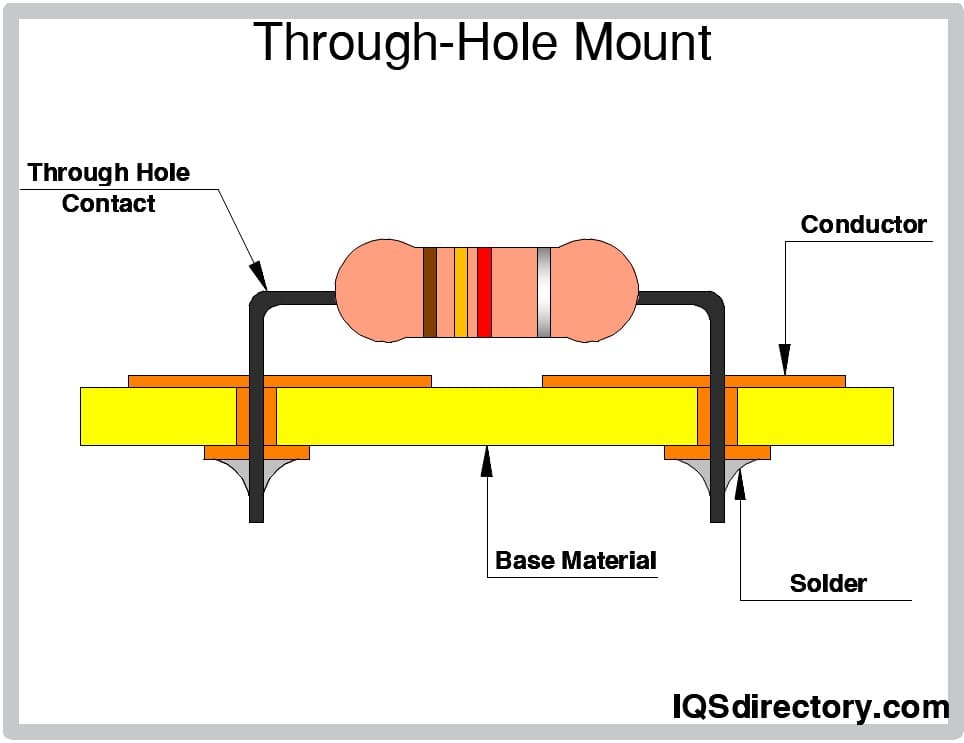
Pin Through Hole - Pin through hole mountings are used when terminating leads are attached to a circuit board through holes or vias placed in a board.
Termination methods vary depending on personal preference with some terminations requiring a specific type. The determining factors are the needs of an application and the stipulations of a project.
In board-to-board and wire-to-board connections, solder terminations are used on through-hole mount or surface mount devices. In through-hole terminations, the terminals are inserted into drilled holes and soldered on the contact pads located on the other side of the board.
With surface mount terminations, the leads and mounting pads are on the same side of the board. Components are placed by hand and soldered using reflow or wave soldering. Terminals are soldered on contact pads on the same side as the connector.
Crimp connections involve compressing electrical wires and cables against a crimp termination or splice band. The compression reshapes the wire strands to create a low-resistance electrical connection, akin to a cold weld.
Crimping is crucial for reliable terminal connections. Improper crimping can result in electrical failures or even fires. Ensuring correct wire preparation, sizing, and using appropriate termination types, tools, and settings are vital for dependable and permanent connections. The crimping process starts with evaluating and measuring the wire's cross-section.
The crimping tool is either a ratchet or manual crimper. The jaws of the crimper cover the entire surface area of the connector and are equipped with crimping dies designed to match the gauge of the wire. Dies are color coded to indicate correct placement of the wire.
The wire to be crimped fits in the barrel of the connector, which is typically 0.25 inches (0.64 cm) in diameter. Once placed, the jaws of the crimper close and apply pressure to the barrel and wire. The compression removes the insulation from the wire exposing the conductors.
A strong connection between the connector and wire is critical for preventing connection failure and collateral damage. A final step in the crimping process involves twisting and tightening the exposed wire to ensure a secure fit.
The stripped exposed wire is inserted into the barrel of the connector until the insulation of the wire touches the barrel. None of the exposed wire should be visible at the entrance of the barrel or past the barrel into the tongue of the terminal.
The connector and stripped wire are placed back in the crimper die in a horizontal position with the barrel side facing upward and the flat side downward. The color of the die on the crimper should match the color of the insulation wire. The slot or die must match the gauge of the wire.
The crimper is placed perpendicular to the connector and stripped wire such that the crimper can firmly hold them. The jaws of the crimper should be placed closer to the tongue of the connector than to the insulation of the wire. Once positioned, the jaws of the crimper are closed with great force such that the wire cannot be removed when it is pulled away from the terminal.
Electrical tape or a heat shrink seal are used to protect the wire and connector of the terminal against exposure to the elements. The adhesive of the electrical tape makes a tight connection while heat shrinking involves applying heat melts plastic material and causes it to deform to the shape of the terminal.
Crimping eliminates the need for soldering wire connections and avoids potential failure associated with soldered joints that become brittle and crack. Terminal manufacturers supply information regarding the appropriate tooling and materials for completing a connection that should be followed to prevent wiring failures.
Ratchet crimp tools provide tactile evidence that the terminal crimp has been fully compressed and have color coding for easy identification of the proper die. Additionally, the jaws of a ratchet crimp tool will not open until the crimp between the connector and wire is sufficiently snug and tight.

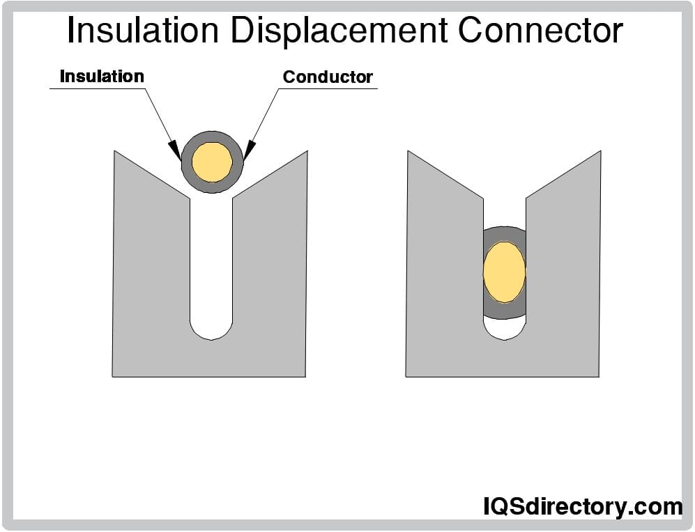
Insulation Displacement Connectors (IDCs) have sharp blades that strip the wire insulation as the wire or cable is inserted. Once properly placed, the exposed area of the wire is cold-welded to the connector terminal, creating a secure and reliable connection. The insulation displacement is commonly used on ribbon cable connectors and telephone and network plugs.
Push-in terminations are reliable and rugged terminations that can be temporary or permanent. Wires are stripped and pushed into the connector or locked in. Although the push-in and locked in methods are most common, there are several variations of push-in terminations. They are quite common and used with several types of connectors. Push-in terminations are restricted to applications that do not have any vibrations that could break or loosen the connection. A vibration rating of an application is required for the use of push-in terminations.

Power supplies are electrical circuits and devices that are designed to convert mains power or electricity from any electric source to specific values of voltage and current for the target device...
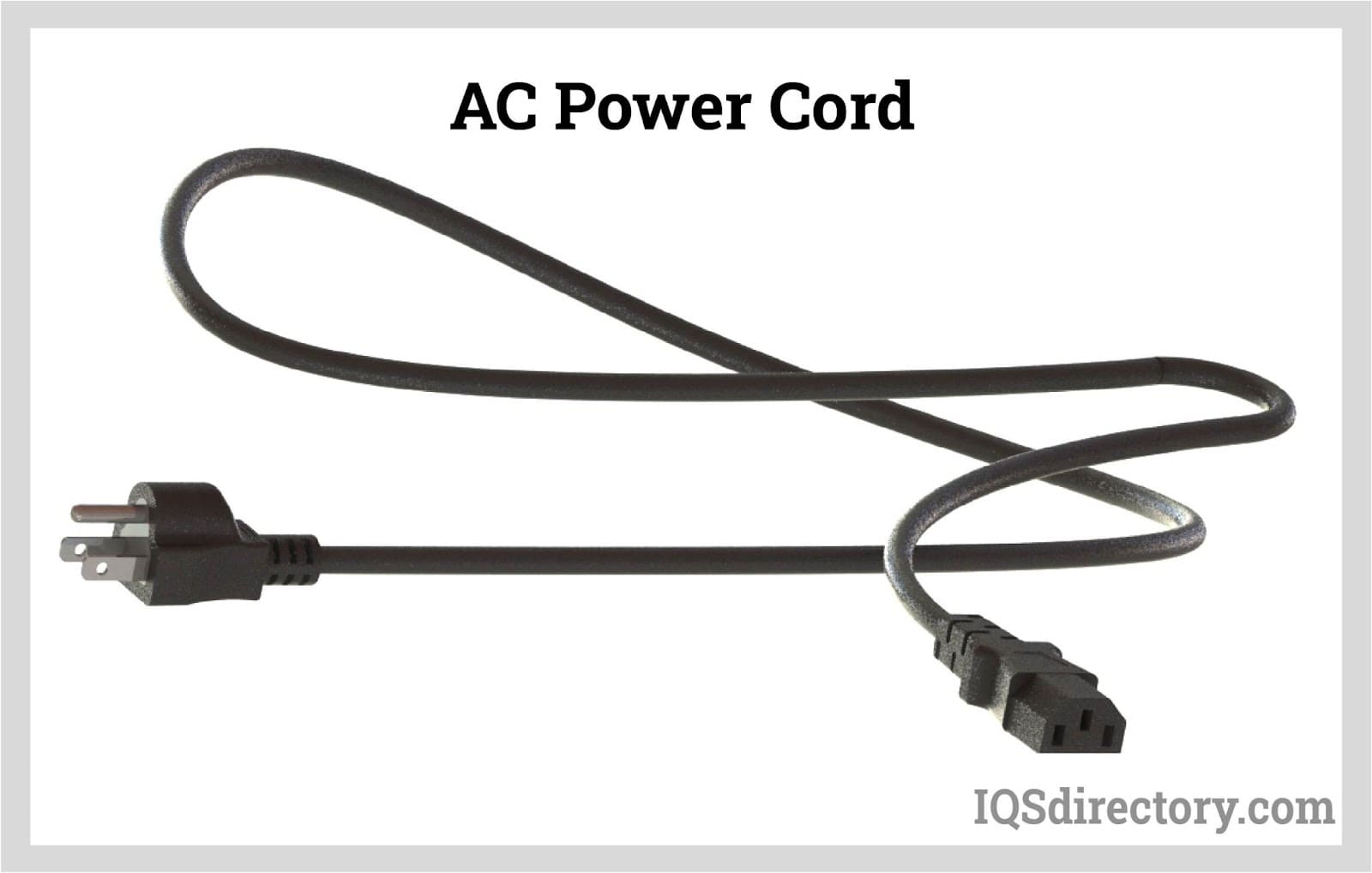
An AC power cord is a detachable way of providing an alternating current of electric energy from a mains power supply to an electrical appliance or equipment. Serving industries like...
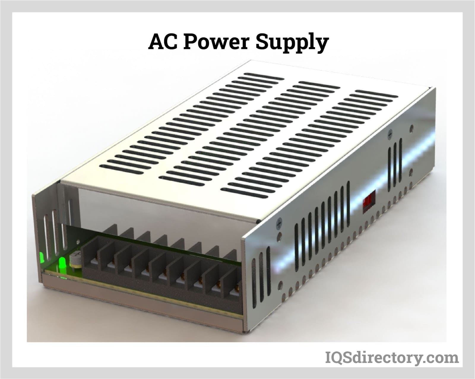
An AC power supply is a type of power supply used to supply alternating current (AC) power to a load. The power input may be in an AC or DC form. The power supplied from wall outlets (mains supply) and...
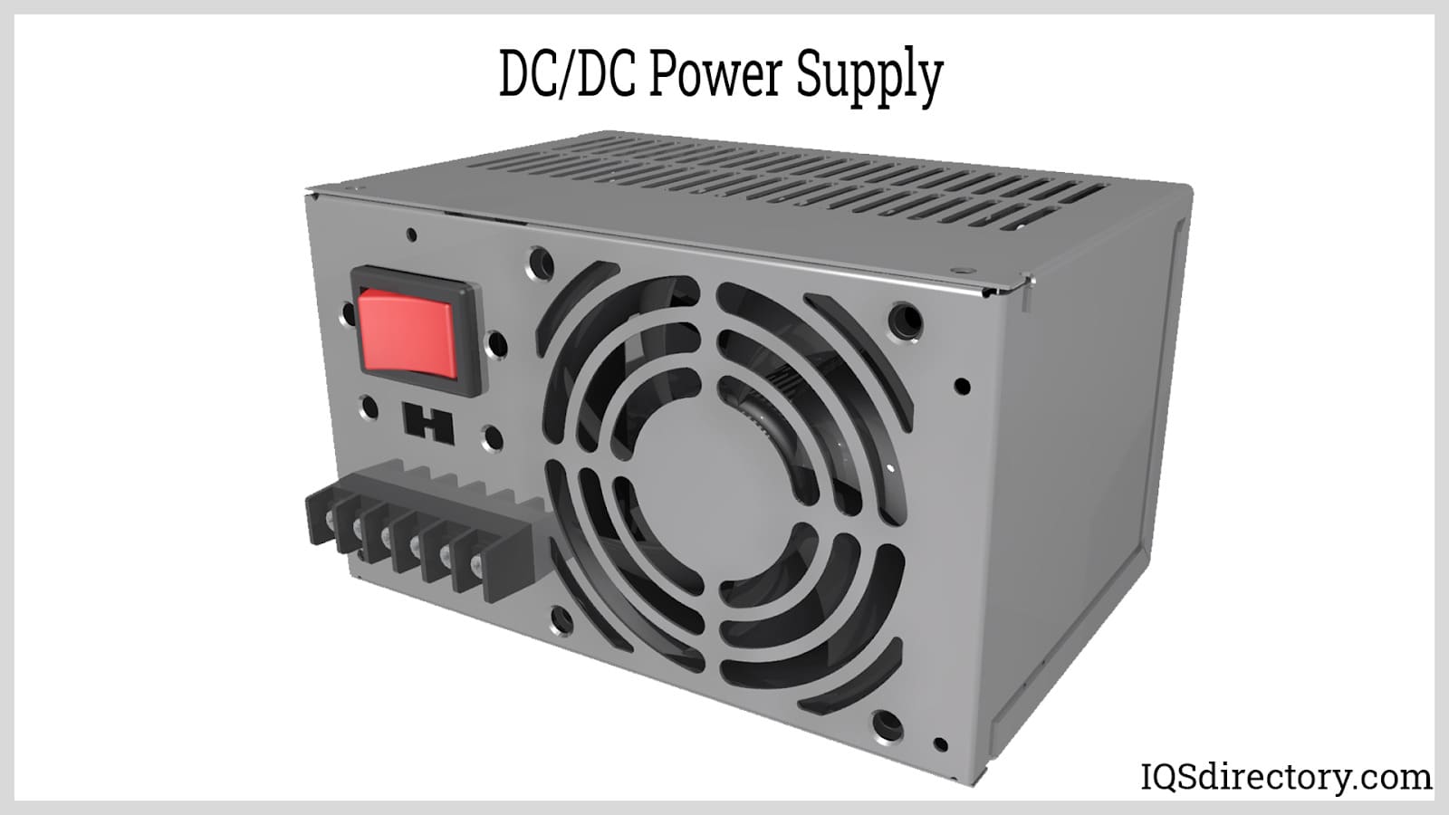
A DC DC power supply (also known as DC DC Converter) is a kind of DC power supply that uses DC voltage as input instead of AC/DC power supplies that rely on AC mains supply voltage as an input...
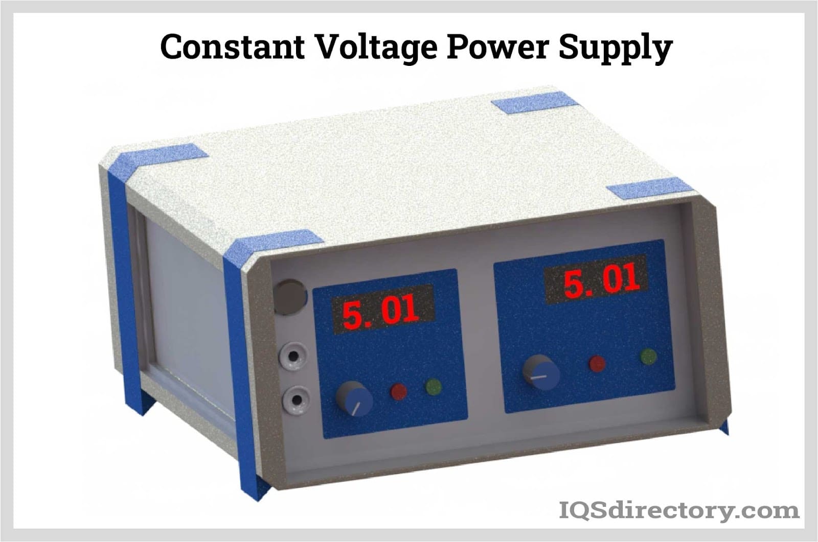
A DC power supply is a type of power supply that gives direct current (DC) voltage to power a device. Because DC power supply is commonly used on an engineer‘s or technician‘s bench for a ton of power tests...
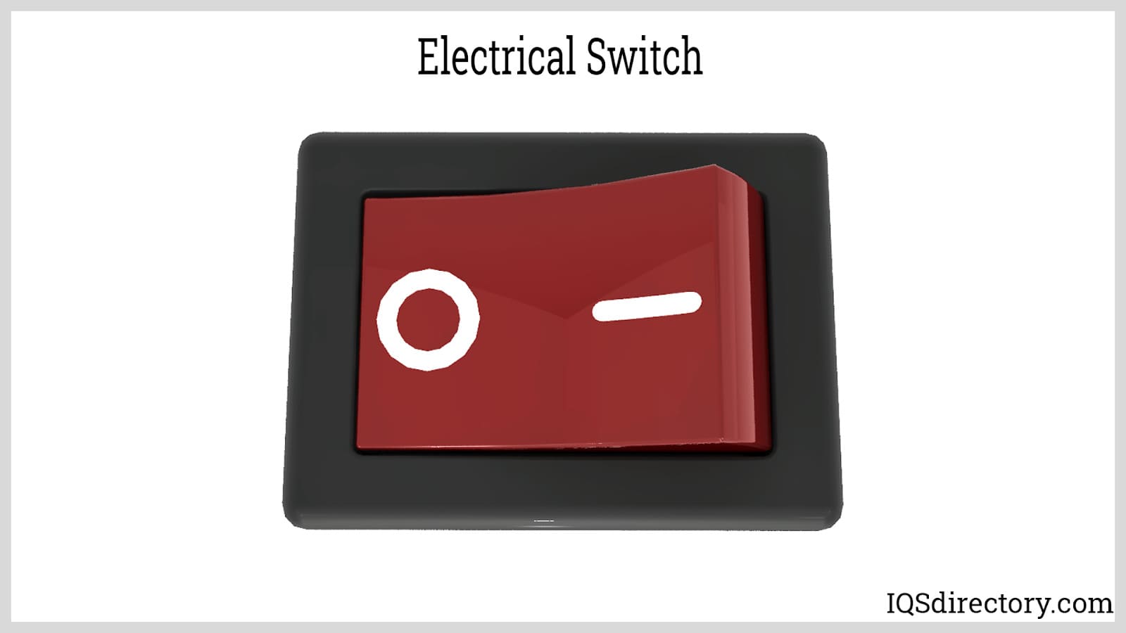
An electric switch is a device – usually electromechanical – that is used to open and close an electric circuit. This disables and enables the flow of electric current, respectively...
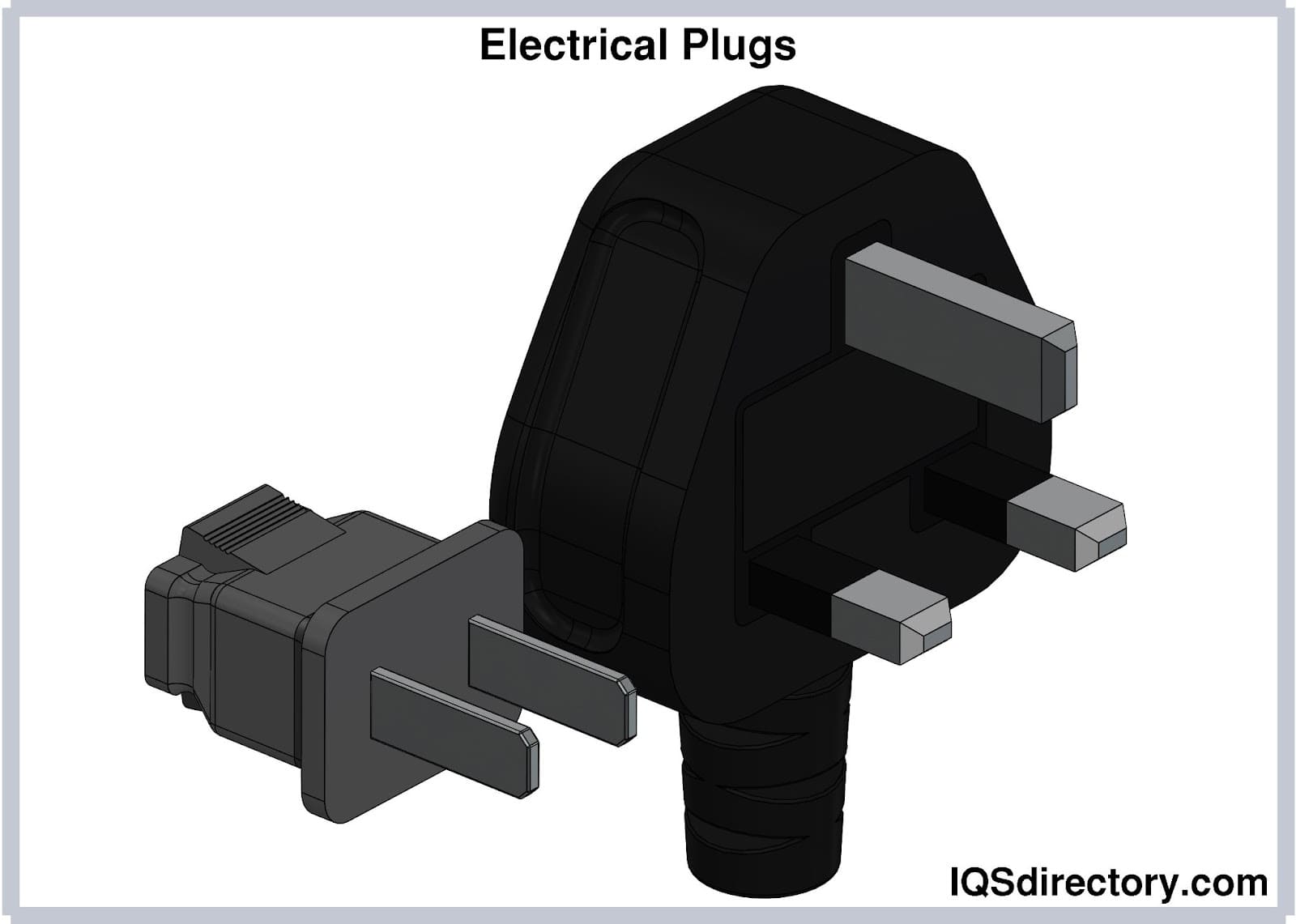
Electrical plugs, commonly known as power plugs, are devices responsible for supplying and drawing current from a receptacle to the circuitry of an electrical appliance...
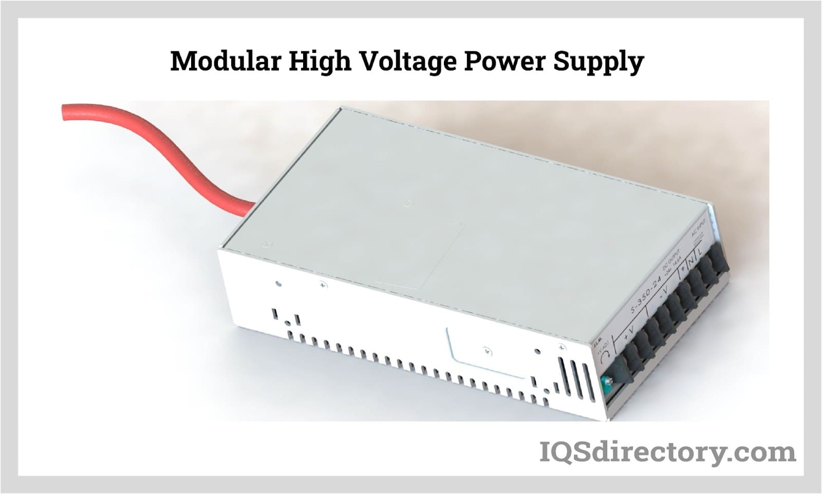
By definition a power supply is a device that is designed to supply electric power to an electrical load. An electrical load refers to an electrical device that uses up electric power. Such a device can be anything from...
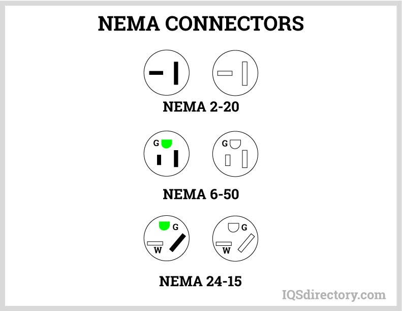
A NEMA connector is a method for connecting electronic devices to power outlets. They can carry alternating current (AC) or direct current (DC). AC current is the typical current found in homes, offices, stores, or businesses...
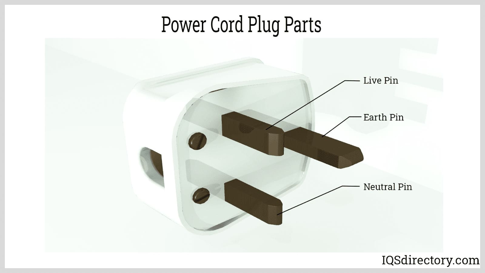
A power cord is an electrical component used for connecting appliances to an electrical utility or power supply. It is made from an insulated electrical cable with one or both ends molded with connectors...
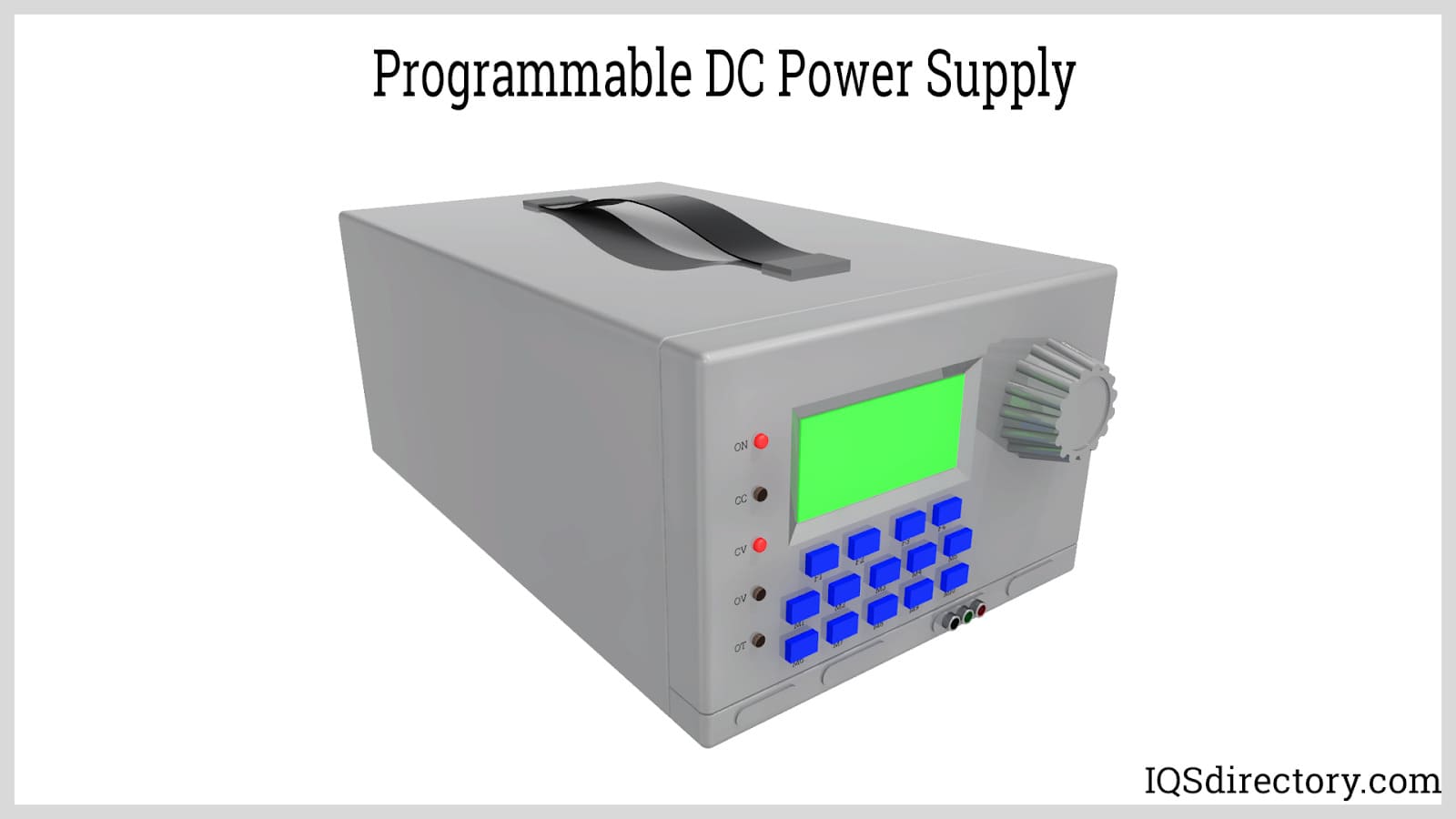
A programmable power supply is a method for controlling output voltage using an analog or digitally controlled signal using a keypad or rotary switch from the front panel of the power supply...
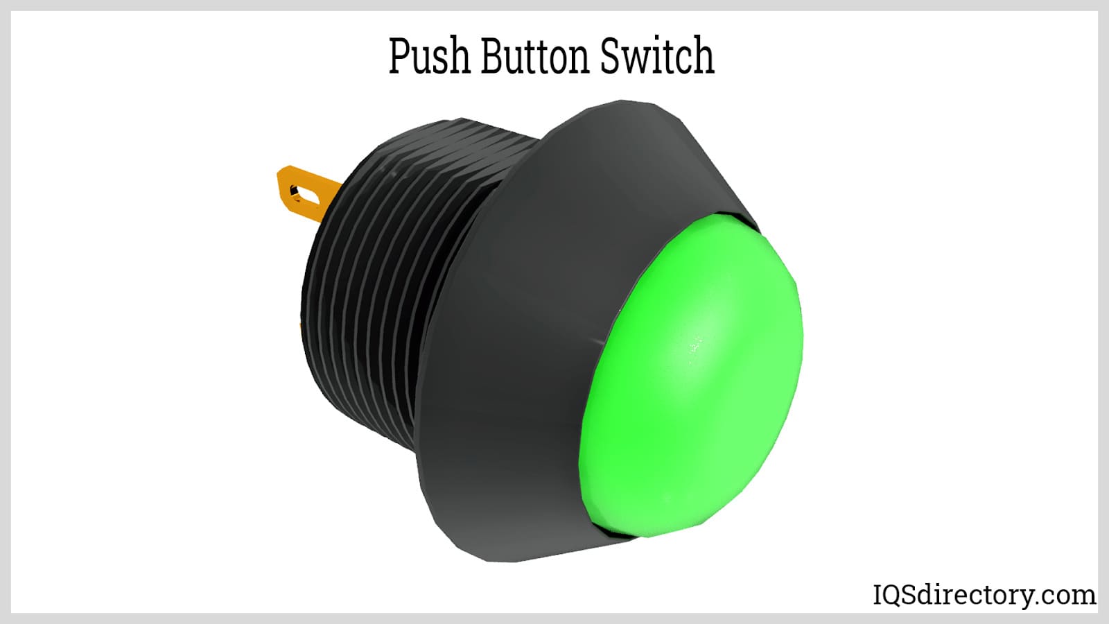
Push button switches are electrical actuators that, when pressed, either close or open the electrical circuits to which they are attached. They are capable of controlling a wide range of electronic gadgets...
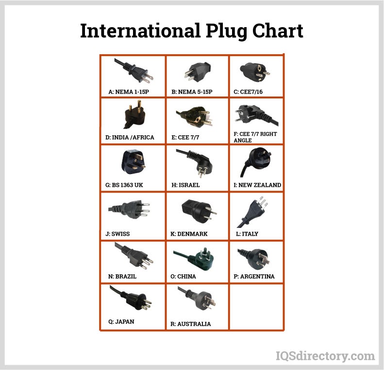
Thomas Edison developed the power distribution system in 1882. He wrapped a copper rod in jute, a soft shiny fiber from plants, as an insulator. The jute wrapped copper rod was placed in a pipe with a bituminous compound...