Gear Drive

Gear drives, sometimes referred to as gear trains and gearboxes, are mechanisms consisting of an assembly of gears, shafts, and other machine elements for mounting the rotating parts...
Please fill out the following form to submit a Request for Quote to any of the following companies listed on
This article will take an in-depth look at speed reducers.
The article will bring more detail on topics such as:
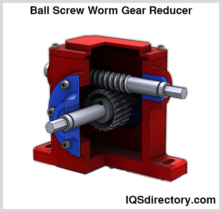
This chapter explores key topics including the essentials of speed reducers, how speed reduction works, and vital considerations when selecting speed reducers.
Speed reducers, also known as gear reducers, are mechanical devices that decelerate power transmission from a motor to machinery. Their primary purpose is to amplify torque from the power source, thereby enabling more substantial work capabilities. Speed reducers accomplish this by using a gear train to modify speed and torque output.
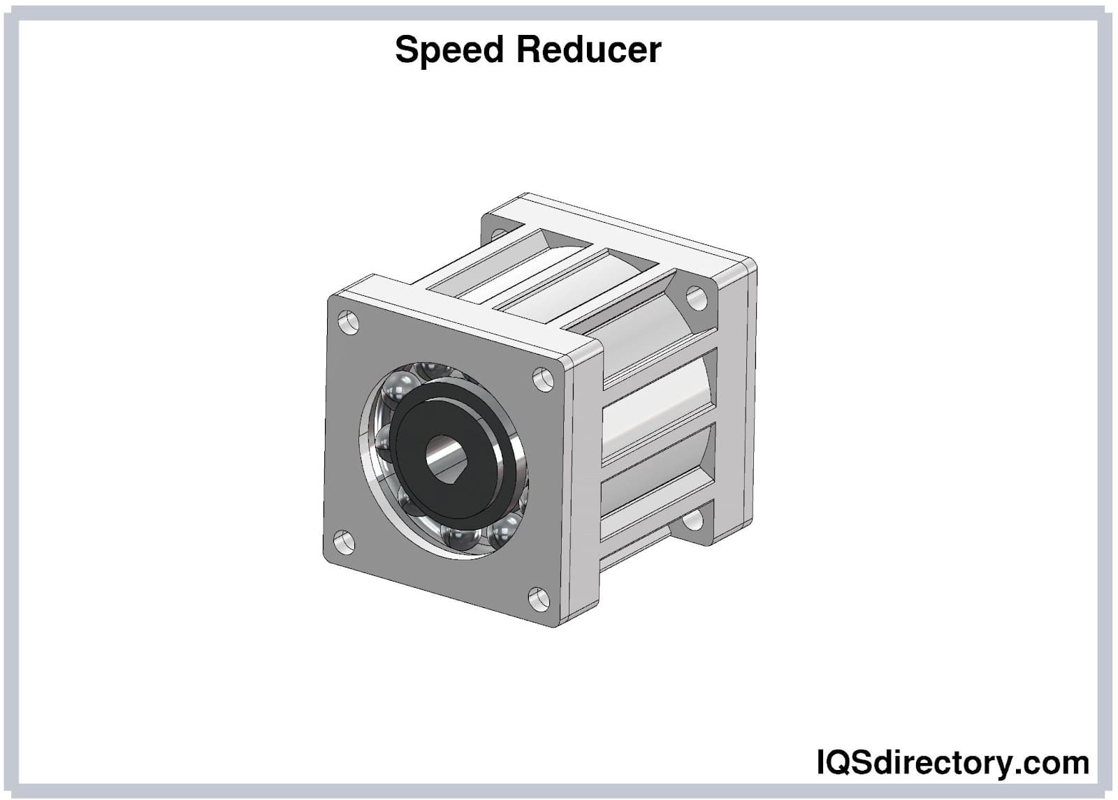
Speed reducers deliver two main functions: they boost the torque delivered by the input source and reduce input speed to ensure the output speed matches the application needs. This is achieved by featuring an output gear with more teeth than the input gear. As a result, even though the output gear operates at a lower speed than the input, it produces increased torque.
Speed reduction, or gear reduction, is understood through the following dimensions:
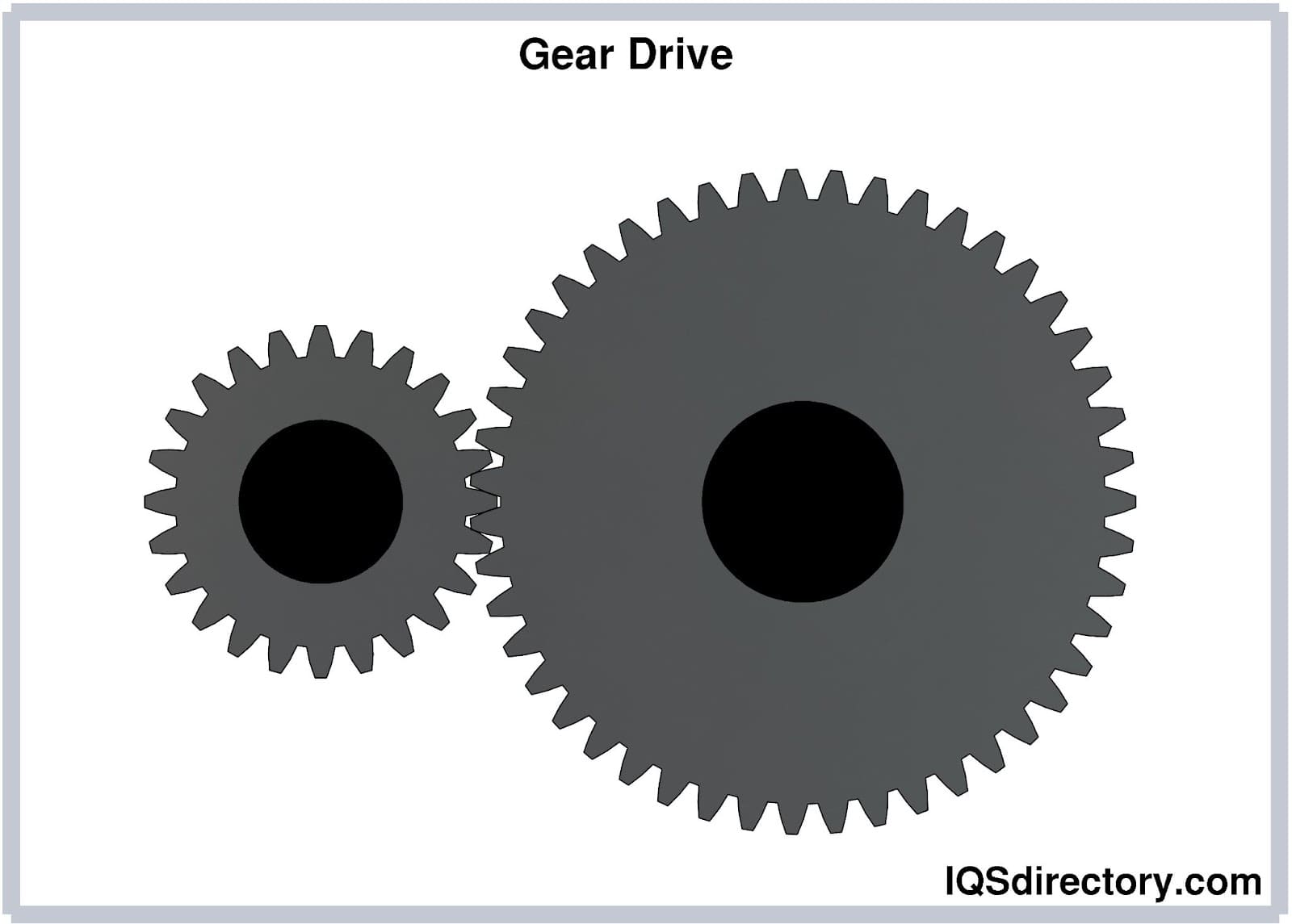
A gear ratio quantifies how varying gear sizes interact to transfer energy. This ratio typically hinges on the gear circumferences, which are pivotal in gear calculations. For instance, if a smaller gear spins twice as fast as a larger gear, the gear ratio would be 2:1, indicating that the output speed is cut in half compared to the input speed.
This principle is applicable in calculating RPM to torque conversions for complex gear reducers with multiple gear pairs. However, only the driver and driven gears are used in gear ratio calculations, while intermediate gears remain irrelevant. To find the gear ratio, count the teeth on both the driver and driven gears: if the driver gear has 7 teeth and the driven gear has 30 teeth, the driver must rotate 4.3 times for one rotation of the driven gear.
The driver gear is the element that imparts energy within a mechanical setup. These gears, with teeth circling their rims, are vital in most mechanical systems, facilitating the transfer of rotational motion and force from one gear to another when meshing. In such systems, gear trains enable the movement of rotary motion and power between machine components.
Known as the follower, the driven gear is the recipient of force from the driver gear. Generally, it is the largest gear in the assembly and comes in various designs depending on specific system needs while playing an essential role in the force transmission within gear trains.
Torque represents rotational force that gear reducers capture and convert into new force and speed while maintaining constant power levels. Gear reducers, comprising one or multiple gears, modulate a motor's torque in correlation to RPM adjustments. This functionality is met through either base-mounted or shaft-mounted gear reducers.
The extent of torque amplification or reduction is dictated by gear sizes. The gear ratio, or size comparison of the gears, determines torque modification. This foundational principle is critical to gearbox operations.
Essential considerations for selecting speed reducers include:
Reducers increase your motor's torque, enabling a receiving part to rotate under a freshly applied torque. Gear reducer manufacturers identify the torque range, in newton meters (N.m), that each reducer can accommodate. Torque density varies across gear reducers, with planetary gearboxes exhibiting high torque densities.
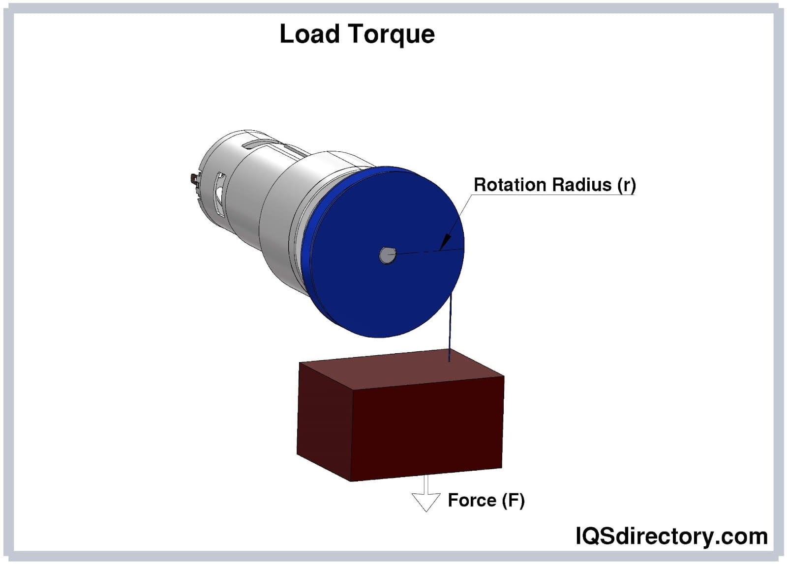
Geometry of the housing and input/output shafts is pivotal when selecting a gear reducer. These geometrical factors significantly influence gear reducer compatibility with equipment, motors, and applied loads.
Operational factors are critical when choosing a gear reducer. Consider operating hours and exposure to harsh environments involving chemicals, extreme temperatures, shock, or vibrations. For instance, in aggregate conveyors, gear reducers experience shock, vibration, and temperature fluctuations in dusty environments.
Gear reducers are vital in slowing down motor speeds. Selecting the correct reduction ratio is crucial for specific applications, as it determines the output speed in relation to the motor's RPM (revolutions per minute).
Owing to the vast array of gear reducers for varied functional requirements, consulting a knowledgeable expert or engineer is essential in selecting the right fit. Initial consideration should focus on the configurations of the input and output shafts to ensure the most suitable gear reducer is chosen.
Motors in certain applications experience shock or cyclic stress. It is imperative to consider these conditions when selecting a gear reducer to ensure it can competently handle elevated torque scenarios.
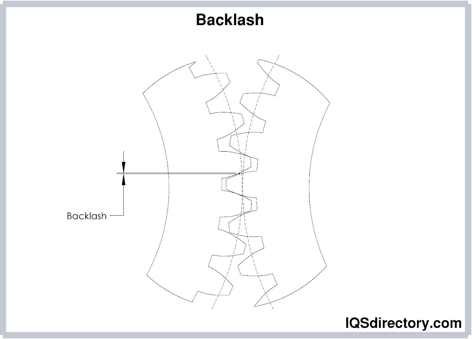
Backlash refers to the play or clearance in the gear engagement within a gearbox, potentially leading to mechanical shock during starts and stops. To prevent premature mechanical breakdown, particularly in applications with intermittent motor operation, gearboxes with minimal backlash, such as planetary gearboxes, are advantageous.
The size, shape, and configuration of the gearbox become critical considerations when dealing with space or profile limitations at the mounting site. Different gear types offer varying efficiencies: planetary gear trains save space, while spur gears utilize more area. In compact applications, gearboxes might integrate as motor mounts; conversely, in larger setups, separate chassis-mounted gearboxes are often necessary.
The different types of speed reducers are essential components in countless industrial automation systems, machinery, and equipment requiring controlled rotational speed and increased torque output. Understanding the various types of speed reducers, their unique construction, transmission principles, and typical applications can help users select the best solution for a specific power transmission or motion control need. Below, we discuss the most common types of speed reducers, including cycloidal, gearbox, gear drive, gear motor, in-line, right angle, magnetic, and hypoid speed reducers, as well as a breakdown by axis configuration.
A cyclo reducer, or cycloidal speed reducer, is a specialized gearbox engineered to reduce the speed of an input shaft by a precise ratio while multiplying torque. Cycloidal gearboxes are known for their robustness, compact size, high reliability, shock-load resistance, and minimal backlash, making them excellent for servo systems, robotics, conveyors, and high-precision automation equipment. The unique cycloidal mechanism consists of an off-center rotating disc, ring pins, and output rollers, enabling high reduction ratios in a small envelope. Cyclo reducers operate with smooth, vibration-resistant motion and longer service lives due to distributed load paths and low friction. However, compared to single-stage spur or shaft-mounted speed reducers, cyclo reducers are less optimal for low ratios below 50:1.
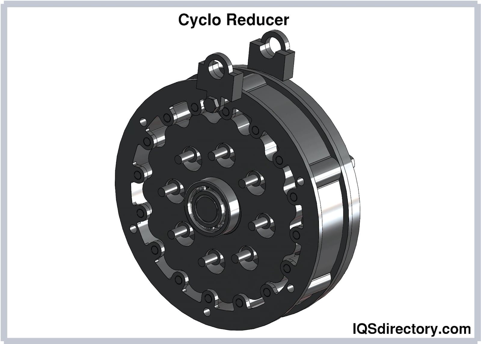
Industries adopting cyclo drives include material handling, automotive assembly, aerospace, food and beverage processing, oil and gas, and the textile sector. Typical cycloidal speed reducer applications range from power transmission in press machines, pumps, extruders, packaging lines, robotics actuators, conveyors, and propeller drives in marine vessels. Cyclo drives offer a compact, maintenance-friendly solution in installations where space optimization is crucial. Their robust construction—often in steel, aluminum, or cast iron—makes them ideal for challenging environments.
The cyclo drive’s unique reduction ratio is computed as R = (P - L) / L, with P representing the number of ring gear pins and L the number of lobes on the cycloidal disc. Unlike conventional gearboxes, input and output direction cannot be reversed, which safeguards against motor back-driving. For comparison, other speed reduction systems like planetary gearboxes or worm gear reducers offer more flexibility for certain configurations, but cycloidal reducers outshine in efficiency and durability in demanding automation tasks.
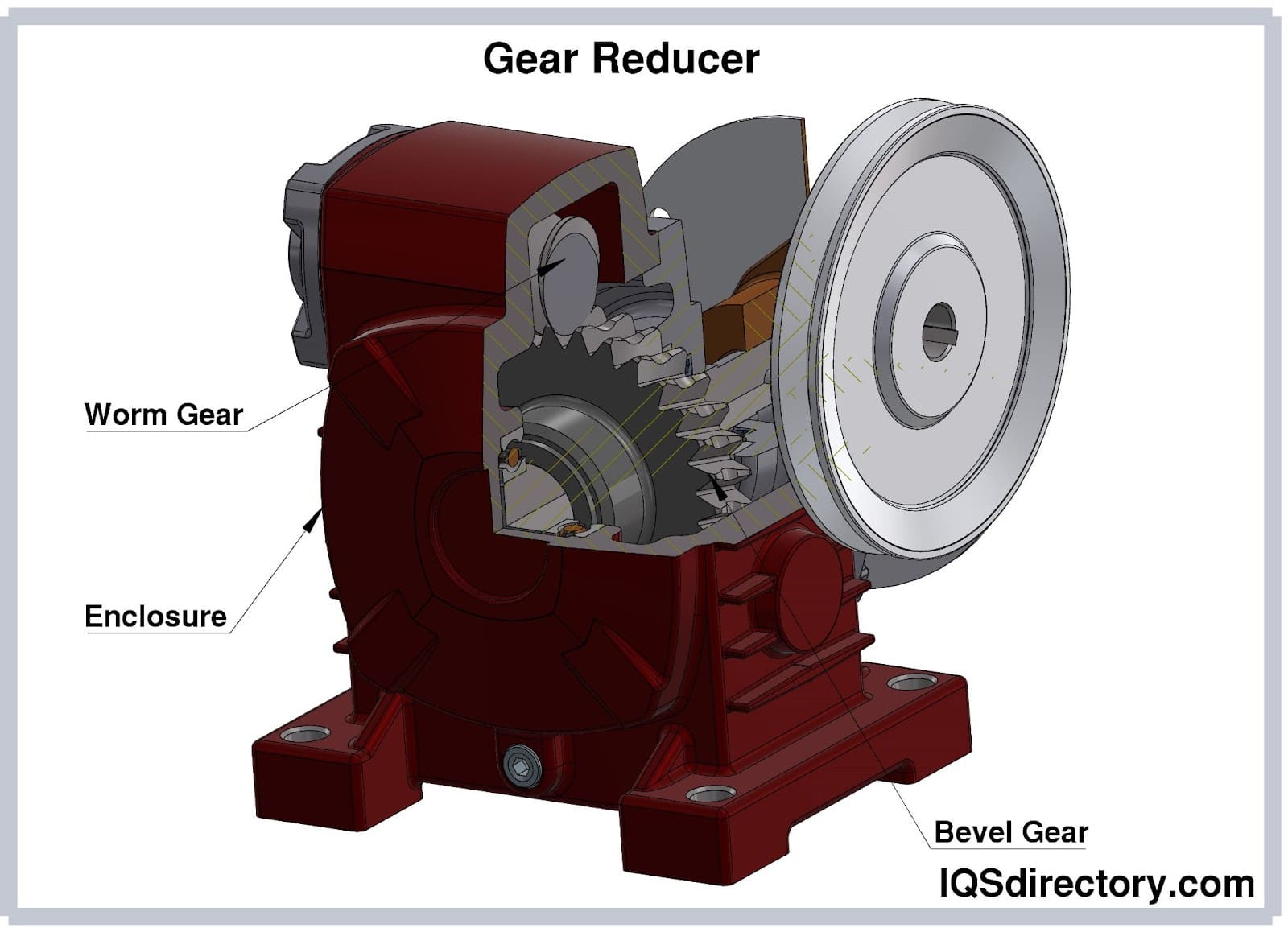
A gearbox speed reducer, also called a gear reducer, is a mechanical assembly designed to modify the speed and torque characteristics of a power source such as an electric motor. Gearboxes use gear trains to decrease input speed while boosting output torque, vital for adapting high RPM motors to equipment requiring low-speed, high-torque drive. Gearbox speed reducers feature a variety of gear types (spur, helical, bevel, worm, planetary) within a protected housing to transmit mechanical power efficiently and with minimal loss. Gear motors often integrate gear reducers directly with electric motors, creating an efficient, compact power transmission solution for conveyors, machine tools, fans, pumps, and other industrial machinery.
Gear drives are pre-assembled power transmission systems used for precise speed and torque adjustment in a variety of industrial applications. Gear drive assemblies employ different gearing configurations to transmit rotational power, manage speed reduction or amplification, torque multiplication, and provide directional changes. Common uses include conveyors, agitators, extruders, and packaging equipment. Choosing the appropriate gear drive depends on factors such as input speed, horsepower, torque requirements, gear ratio, and system durability.
A gear reducer, also known as a gearbox or gearmotor, is a mechanical transmission system that links a motor to a driven load, enabling precise adjustment of torque and rotational speed. Gear motors integrate an electric motor with a speed reducer in a single compact, factory-assembled package. This design provides improved performance, reliability, and ease of installation in automated equipment, food processing, packaging, and assembly lines. Key benefits include enhanced energy efficiency, reduced mechanical footprint, and improved process control by matching motor output to the specific requirements of the driven machinery. Standard options include AC gear motors, DC gear motors, and brushless gear motors, each suited to different environments and performance needs.
Gear reducers—sometimes referred to as reduction gears, gearboxes, or gear reduction boxes—are integral to power transmission systems that require adapting the speed and torque delivered by high-speed motors. Most gear reducers use a combination of small and large gears to achieve the desired gear reduction ratio, resulting in controlled rotation and optimized torque for a wide range of applications. For instance, in a two-gear system, a small pinion gear drives a much larger gear: if the smaller rotates twice for every revolution of the larger, the speed is halved and torque correspondingly increased. Adjusting gear ratios can satisfy industrial requirements for conveyors, cranes, mixers, wind turbines, and more where torque demands vary. Advanced reducer technologies now support higher mechanical efficiency, noise reduction, and improved thermal management to support today’s demanding industrial requirements.
In-line gearboxes transmit the rotational speed from a motor to an output shaft arranged parallel (or co-axial) to the motor’s axis. This configuration is valued for direct, efficient torque transfer and is widely implemented in machine tools, robotics, packaging equipment, and drives requiring compact profiles and high alignment precision. The choice between coaxial and slightly offset configurations depends on system requirements for load handling, space, and efficiency. Below are the main gear types utilized in in-line gear reducers:
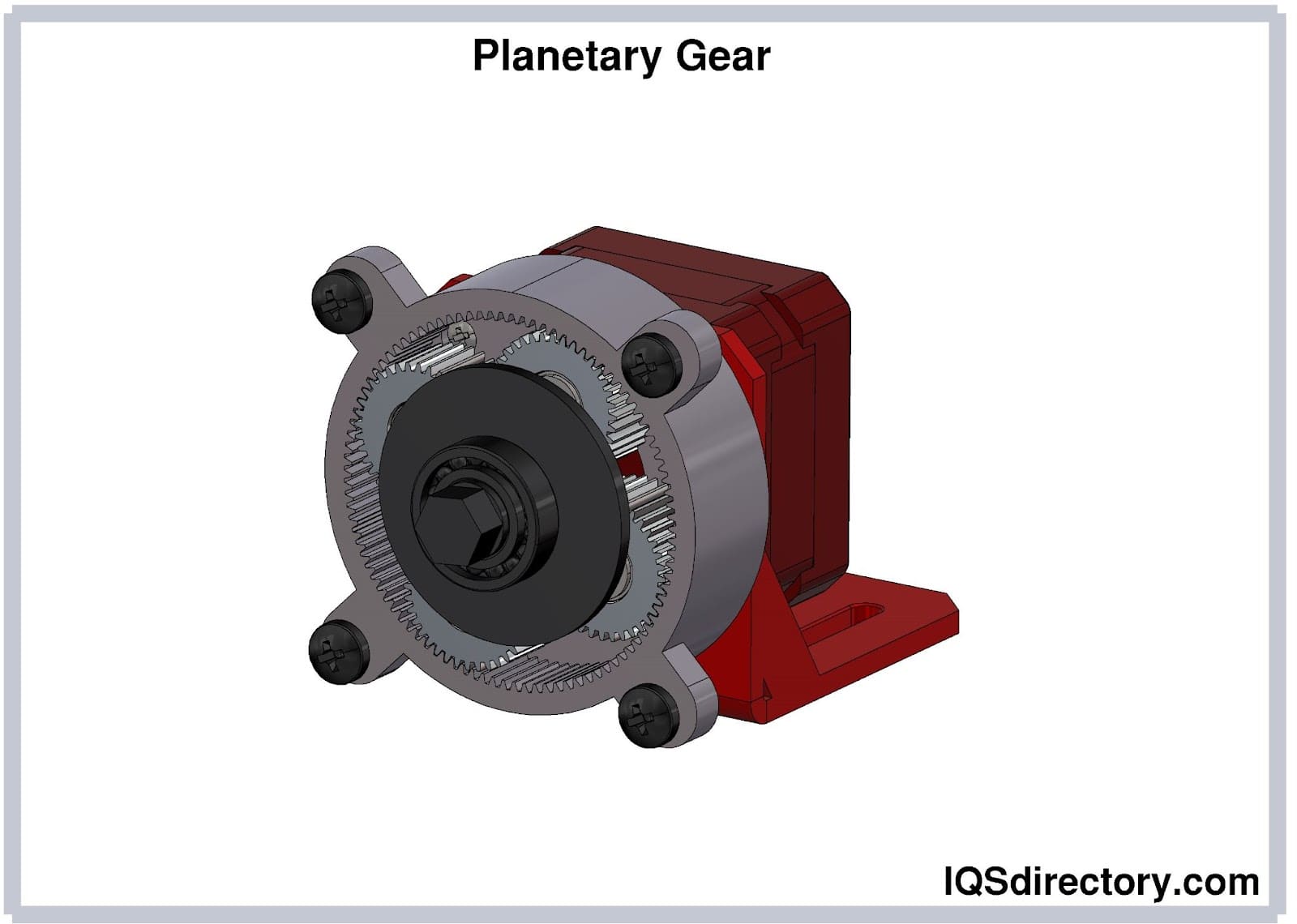
The planetary gearbox, or epicyclic gearbox, is distinguished by its coaxial (aligned) gear arrangement, featuring a central sun gear, planet gears, and an outer ring gear. This design ensures high load sharing, superior torque density, compactness, minimal backlash, and impressive efficiency (often exceeding 95%). Planetary gears are ideal for dynamic and precise applications like robotics, CNC machinery, wind turbines, mobile vehicles, and automation lines where compactness and high output torque are required. While highly efficient, planetary reducers can be more costly and require specialized maintenance yet deliver exceptional performance for heavy-duty, precision, and cyclic duty environments.
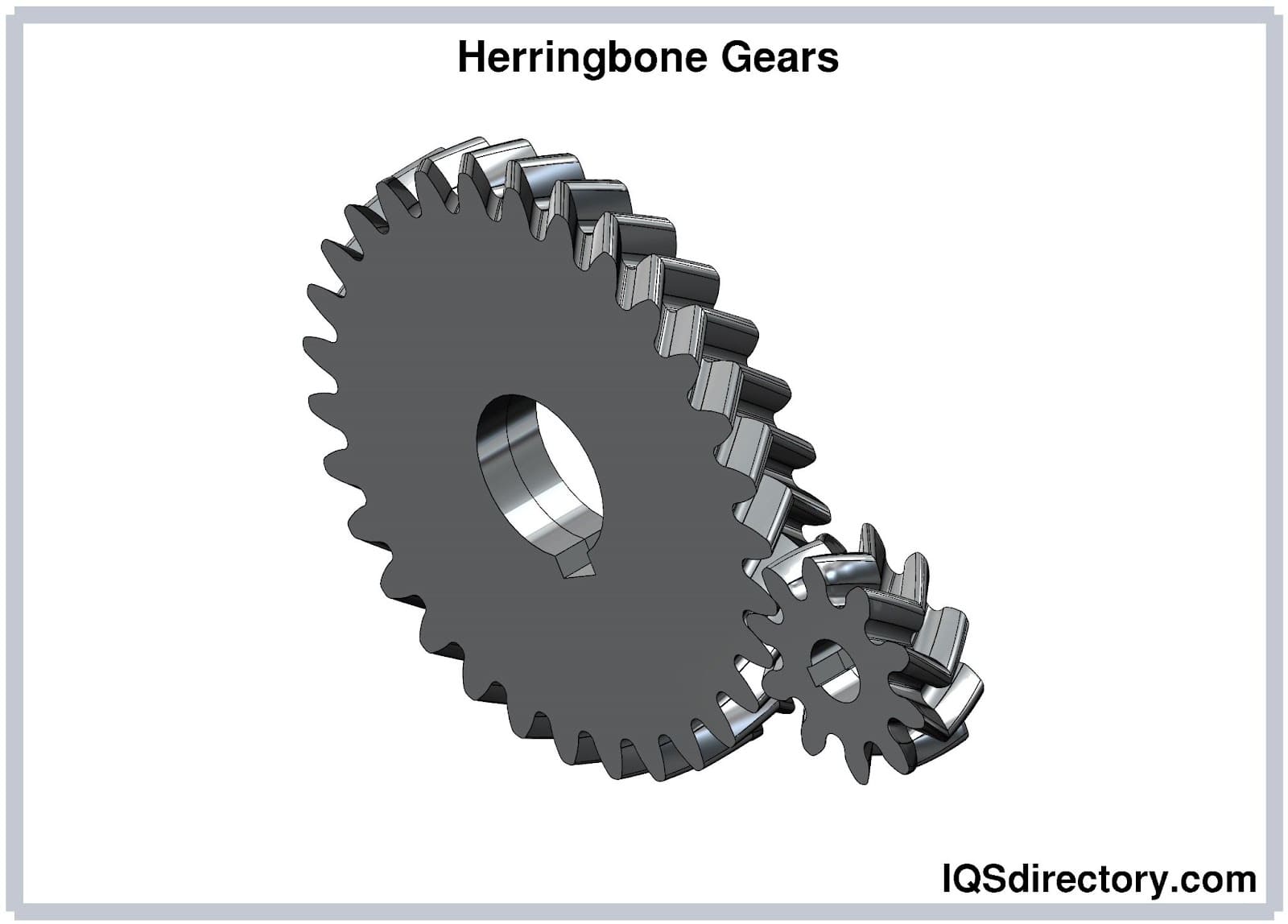
Herringbone gears, a special form of double helical gears, combine two sets of opposing helical gear teeth to neutralize axial thrust. This design achieves smoother, quieter, and more efficient power transmission—making them ideal in heavy machinery, press drives, industrial compressors, and high-torque oil and gas equipment. Herringbone gearboxes are valued for long service life, stable operation, and capability to handle large loads with minimal vibration.
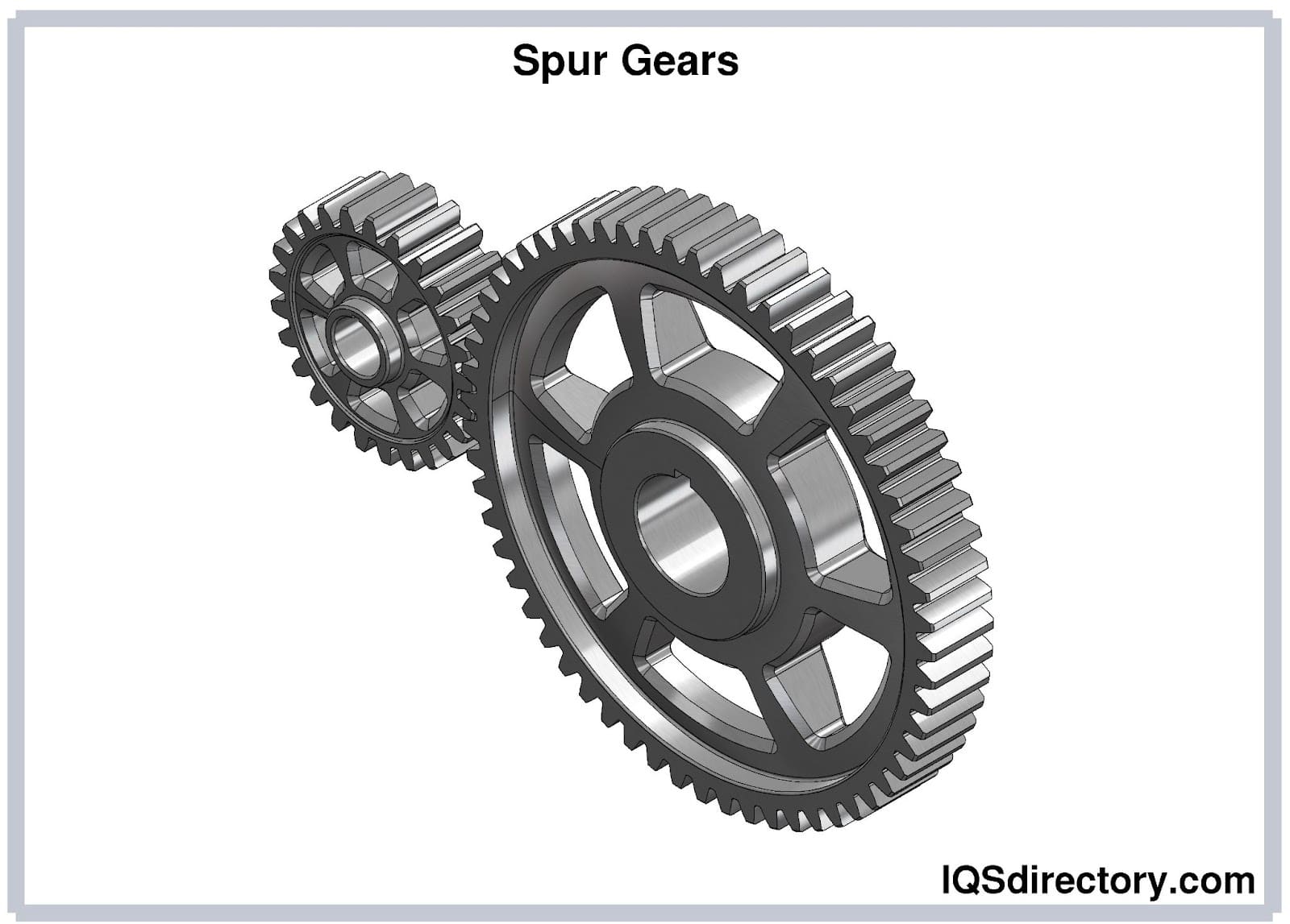
Spur gears are the most basic and widely used type of gear, featuring straight-cut teeth positioned parallel to the gear shaft. Known for simplicity, reliability, and cost-effectiveness, spur gearboxes are ideal for moderate to low-speed applications that do not require extremely high torque. Their inherent design results in higher noise output compared to helical or bevel gears at high speeds, but they remain a popular choice for conveyors, printing machinery, and material handling systems.
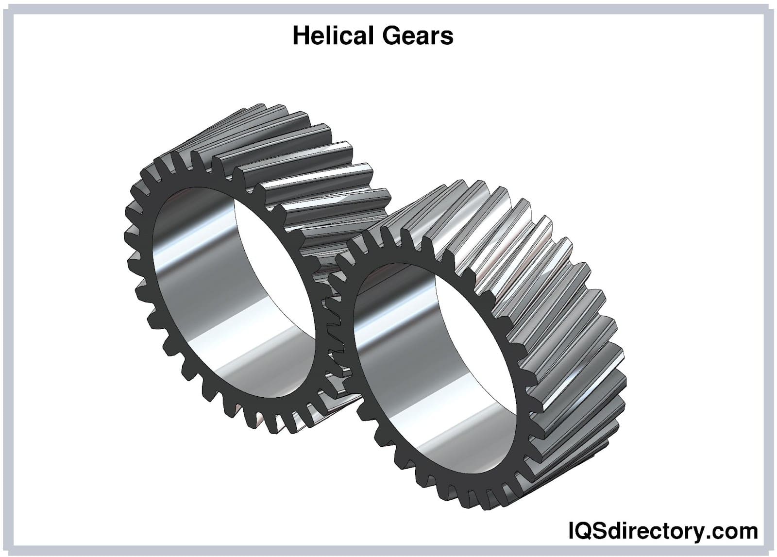
Helical gears feature angled teeth, enabling more gradual and quiet meshing compared to spur gears. This allows helical gear reducers to transmit greater power at higher efficiency while minimizing vibration and noise—critical for high-speed conveyors, blowers, and precision drives. Note that axial forces are produced and must be managed using appropriate bearings, limiting their use in some ultra-high-torque applications.
Right angle gearboxes, including “T” type speed reducers, feature input and output shafts at a 90-degree orientation. These gear reducers utilize hardened steel worm gears, phosphor-bronze wheels, and precision bearings (such as Timken) for durability and efficient torque transfer. Commonly available with reduction ratios between 10:1 and 100:1, right angle gearboxes are indispensable in installations where space constraints or motion redirection are critical, such as in conveyor systems, packaging lines, and transfer machinery.
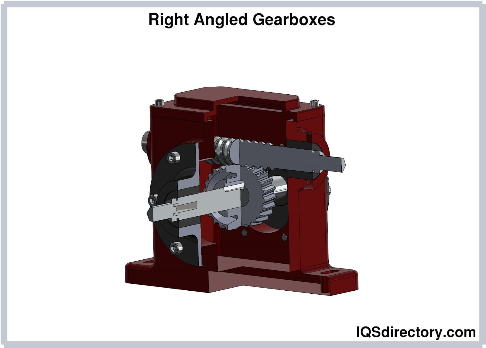
These gearboxes come in standard sizes with customizable shaft extensions and find application in both heavy industrial and precision automation. Their 90-degree output orientation facilitates system design in tight or uniquely shaped workspaces. Below are key right-angle gearbox types:
Worm gear reducers feature orthogonal input and output shafts, with the worm engaged at 90 degrees to the worm wheel. This design easily achieves high reduction ratios and delivers smooth, virtually silent operation, with the added advantage of non-reversibility—preventing back-driving and enhancing system safety. Worm gear speed reducers are also relatively compact and cost-effective compared to other types, making them popular in lifts, hoists, conveyors, and positioning equipment. Note that worm gears are less efficient at high loads and may require improved cooling or pairing with auxiliary gear trains for heavy-duty or continuous-duty service.
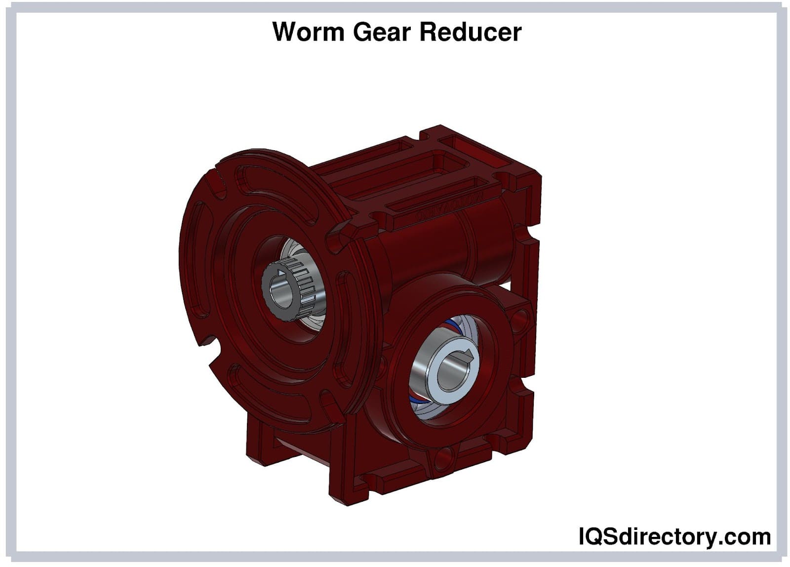
Performance, efficiency, and heat buildup are critical considerations for worm gearboxes—especially in continuous-duty cycles. Pairing worm gear reducers with helical or planetary stages can further enhance performance in demanding or multi-axis drive systems.
Bevel gear reducers use conical or spiral-cut gears to reroute shaft rotation at a right angle, making them compact and robust for applications that require significant torque transmission and directional changes. These gearboxes are often driven by three-phase induction motors or servo motors for flexibility and precision in motion control. Their smooth, efficient, and quiet operation, combined with durable construction, makes bevel reducers common in high-capacity conveyors, mining machinery, and agricultural vehicles. They tend to require more investment and periodic maintenance, but deliver strong energy efficiency and reliable longevity in demanding equipment.
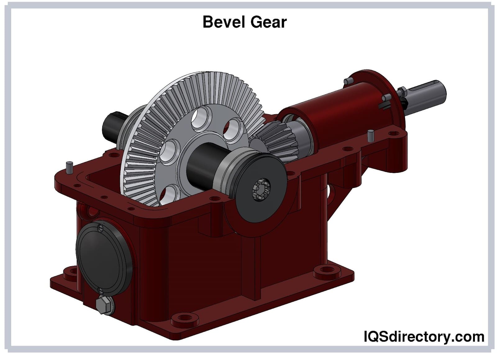
Industrial and municipal facilities relying on continuous-duty and high-load drive systems frequently select bevel gear reducers for their power density and reliability.
Magnetic speed reducers utilize advanced magnetic coupling to adjust input speed and output torque without direct metal-to-metal contact. This innovative technology eliminates friction-based wear, enables oil-free operation, and drastically reduces maintenance costs and downtime. Magnetic gearboxes excel in harsh and contaminant-sensitive environments where traditional gear lubrication is problematic, such as aerospace, food processing, cleanrooms, or remote installations. While torque output is somewhat reduced versus traditional gearboxes, magnetic reducers shine in reliability, operating temperature versatility (from -200°C to 350°C), silent operation, and service life—particularly for mission-critical systems where contamination and wear must be minimized.
By preventing particle contamination from gear wear, magnetic speed reducers also support extended service intervals and enhanced cleanliness, helping industries meet strict reliability and regulatory demands. The tradeoff for these benefits is a more complex structure, higher weight-to-power ratio, and a typically higher upfront cost.
This technology is ideal for challenging industrial, aerospace, and research environments that demand fail-safe drive operation with minimal intervention. Common applications include satellite drive systems, laboratory equipment, and highly sensitive production processes.
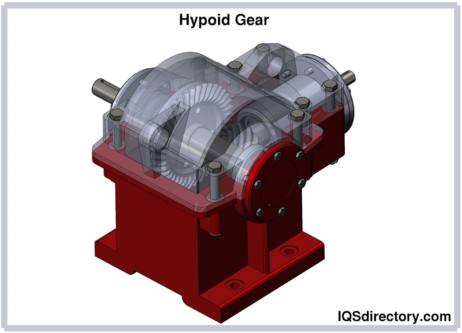
A hypoid speed reducer employs hypoid gears—spiral gears whose axes do not intersect, resulting in offset shafts and a larger, more durable contact area than standard bevel gears. The offset and spiral tooth geometry permit efficient power transmission, reduced noise, and increased load capacity, while also requiring specialized lubricants to manage high-pressure sliding motion. Compared to worm gear reducers, hypoid gearboxes provide higher mechanical efficiency and compact designs, making them suitable for automotive axles, robotics, conveyors, and high-performance industrial machinery. Multiple teeth are engaged at once, distributing load and minimizing wear, which supports reliable high-torque operation under challenging industrial conditions.
Typical hypoid gearbox applications include heavy-duty transport equipment, machine tools, and high-precision motion control systems. Their low-noise, high-efficiency performance enables smoother, longer-lasting operation compared to traditional right-angle gears.
Speed reducers are also classified by the arrangement of their input and output shafts (axes), which directly affects installation layout, transmission performance, and application suitability:
Orthogonal axis (right-angle) gear reducers—such as bevel gearboxes—feature input and output shafts situated at 90 degrees to each other. While generally delivering slightly less precision due to single-side pinion support, their space-saving design makes them excellent for distributing power in confined applications and job-site machinery. Standard reduction ratios include 1:1 and 1:2, suitable for moderate speeds under 1000 RPM where directional change is required.
Skew axis gear reducers feature non-parallel, non-intersecting (offset and perpendicular) input and output shafts. This arrangement ensures greater tooth engagement, which increases contact ratio, torque output, and smoothness in power transmission. Skewed axis reducers are valued for applications where spatial flexibility and improved load distribution are necessary.
Parallel axis gear reducers have input and output shafts that are parallel, using gears such as spur or helical for high-precision and efficient torque transmission. They are commonly used in heavy-duty elevators, cranes, conveyor systems, and blending machinery where robust, accurate, and consistent performance is paramount.
This section explores various methods to enhance the performance of speed reducers. It will also cover essential maintenance practices for speed reducers.
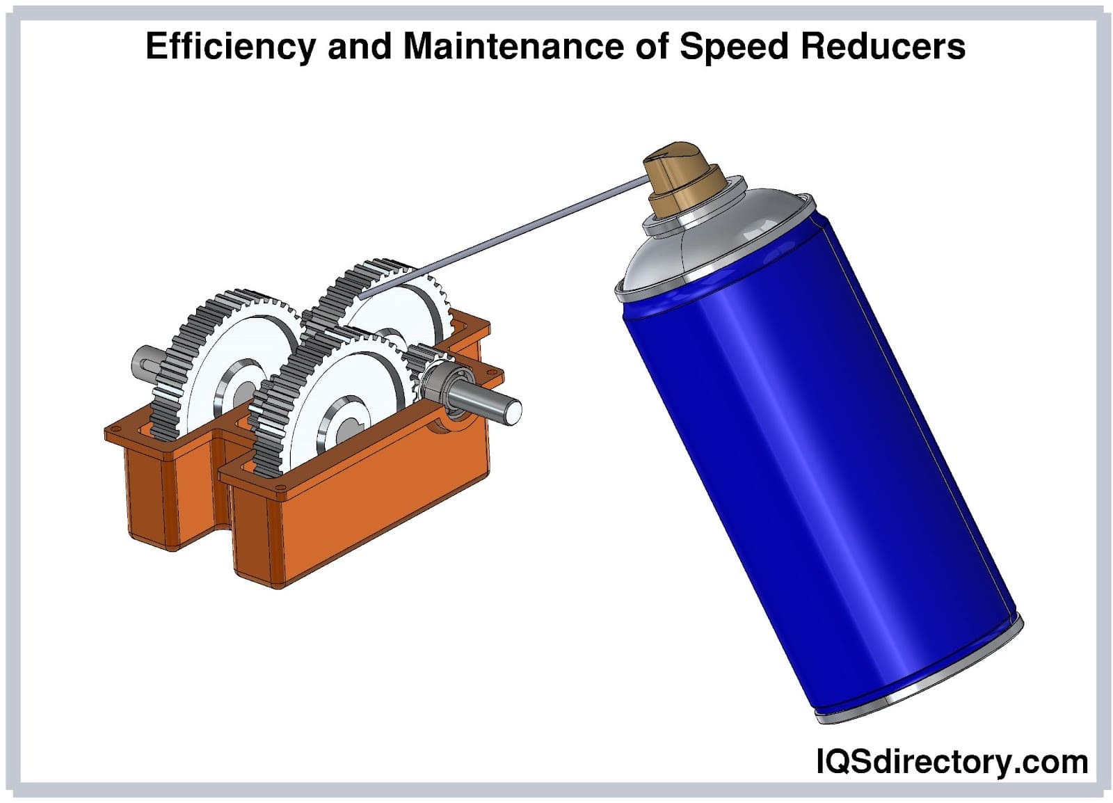
Consider the following strategies to boost the effectiveness of speed reducers:
Prior to market release, gear motors must undergo frequency testing. Monitoring mechanical vibrations is crucial, and your gear motor supplier should be skilled in using vibration analysis tools to prevent harmful frequencies.
Accurate measurement of starting torque, output torque, and rated torque is essential for effective motion transfer and ensuring that the machine or application operates correctly.
When choosing between two models, energy efficiency of the speed reducer is another key aspect to evaluate. The placement of the gear train, the type and positioning of rolling bearings, and the surface finishing of components all contribute to enhancing system performance. Rolling bearings can be implemented and arranged in various configurations.
Incorporating rolling bearings within geared systems minimizes friction among the numerous moving components, leading to notable energy savings.
These components reduce friction less effectively than rolling bearings. However, they help to minimize axial motion caused by repeated axial movements.
Various methods, including the use of rolling bearings, washers, and plain bearings, can be employed to reduce vibrations. Over time, incorporating these components will enhance the gear motor's performance. With reduced vibration levels, the gear motor will operate more accurately, run more quietly, and have a longer lifespan.
The most common reason for premature gearbox failure isn't the quality of the gearbox itself, but rather the operating conditions and service factor it was designed for. Proper maintenance is crucial, including ensuring continuous lubrication of all gearbox components and replacing the lubricant when it depletes due to mechanical stress and heat. Additionally, correct mounting of the gearbox is essential to minimize vibration and stress. Always verify that the alignment between the motor and gearbox, as well as between the gearbox and the driven load, stays within the permissible limits. Below are some key steps for maintaining gear reducers.
Overheating often signals insufficient lubrication in the gear reducer. Regularly monitoring the surface temperature of the gear reducer can help prevent overheating. This issue can arise from a lack of lubricant, which increases friction between the gears. Additionally, overheating might occur if the gear spacing is too tight or uneven. Adjusting the gear gaps can help mitigate this problem. Proper maintenance of the gear reducer will ensure its reliable performance for many years.
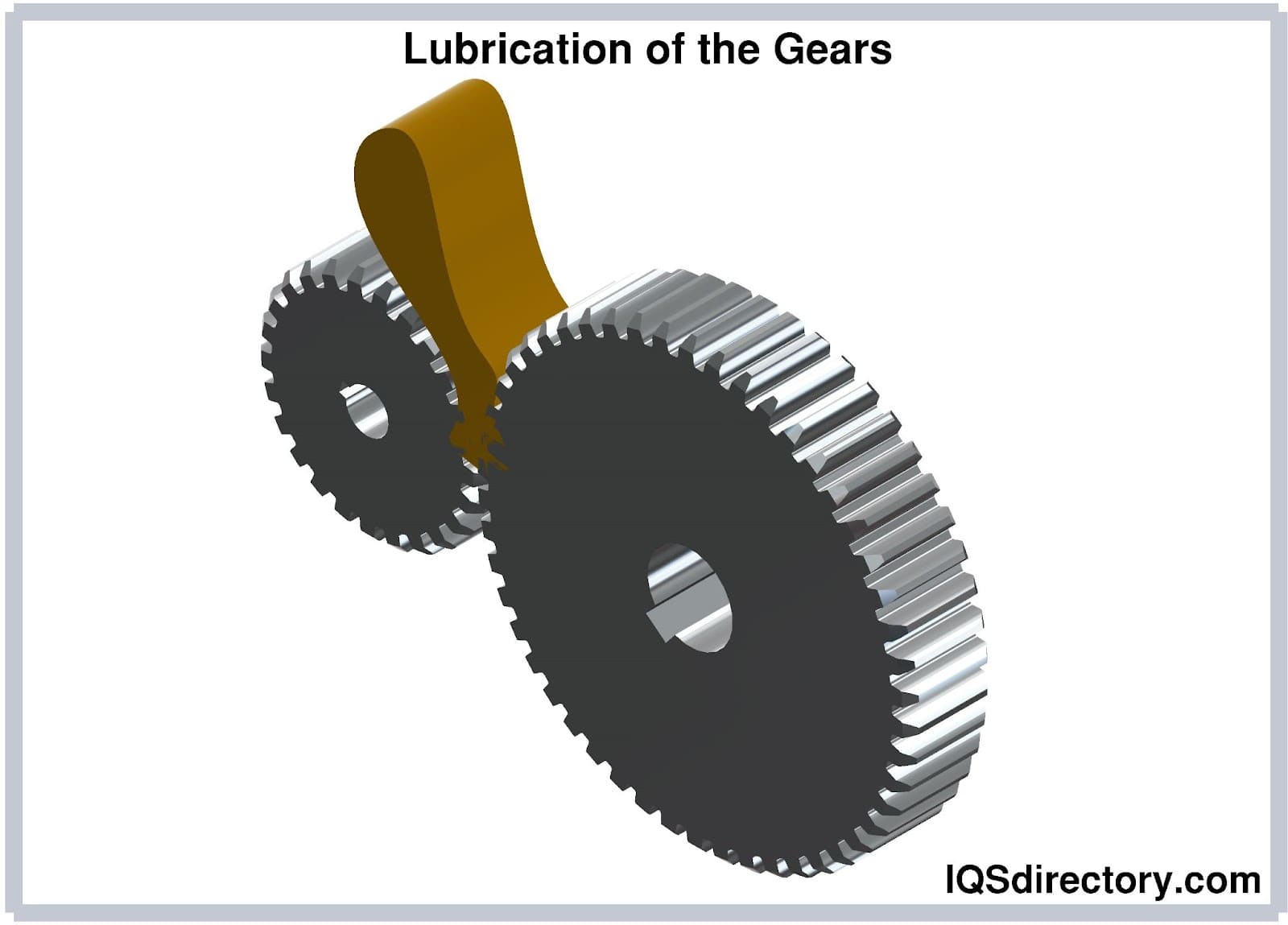
Every manufacturer of gear reducers supplies or recommends the proper lubricant for their devices. To improve performance, the lubricant must have the necessary characteristics. Filtering the lubricant to remove impurities may be necessary at first during the break-in process. The lubricant's quality and level should be checked regularly.
Noise is often the initial indicator of issues with a gear reducer. To evaluate it, operate the gear reducer without a load. Persistent noise and vibration suggest that the gear reducer may need to be overhauled or replaced. Disassemble the gearbox, and address any issues by smoothing out any rough or damaged gears. Check and adjust the gasket to eliminate any clapping sounds. Ensure the housing is kept clean by regularly cleaning the bearings and the interior. Inspect both the housing and gears to confirm they meet the required standards.
Lubricant is essential for the proper functioning of a gear reducer. Inadequate seals can allow dust and water to enter, potentially causing significant damage to the gears.
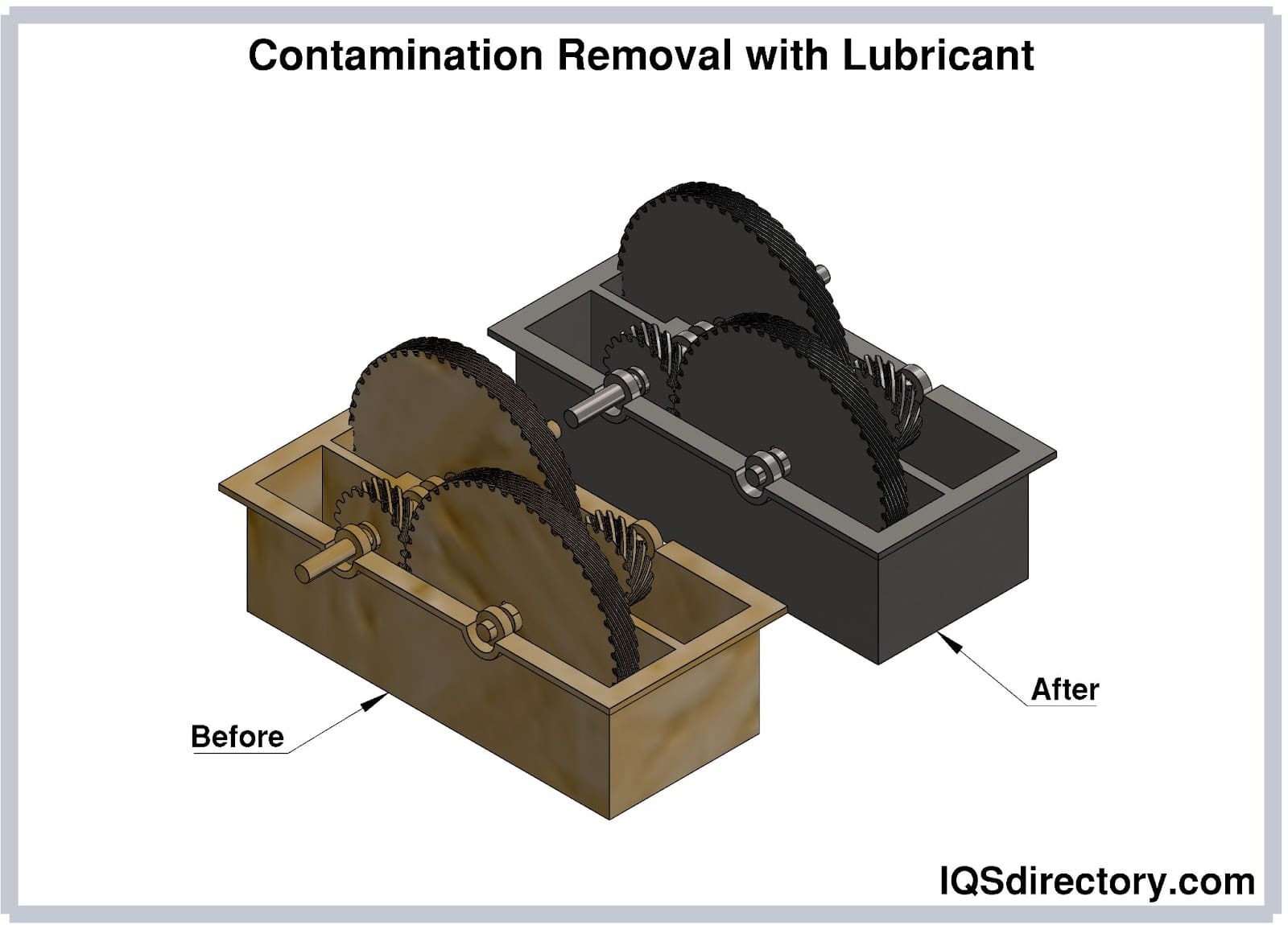
Ensure that all covers, vents, and drains on gear reducers are properly sealed and that they are stored in a clean, dry, and climate-controlled environment. Even when not in use, the gear reducer's lubrication cycle must be maintained. Periodically rotate the gear reducer to promote even distribution of the lubricant.
Gearboxes have a number of features that influence their usefulness for various applications. When selecting a gearbox, it's critical to consider your individual application in order to find a solution that fits all of the design criteria. Once you've decided on a gearbox, it's critical to correctly install and maintain it in order to get the most out of it.
As discussed in the article, the selection, installation, and maintenance of a speed reducer are possible with the understanding that:

Gear drives, sometimes referred to as gear trains and gearboxes, are mechanisms consisting of an assembly of gears, shafts, and other machine elements for mounting the rotating parts...
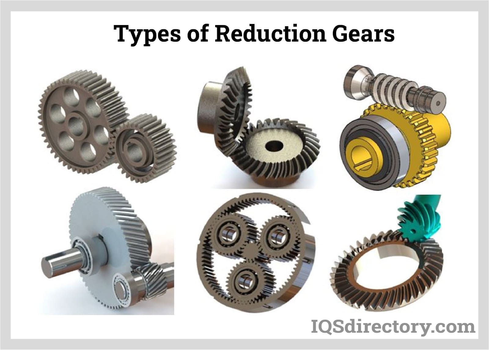
A gear reducer is a mechanical system of gears in an arrangement such that input speed can be lowered to a slower output speed but have the same or more output torque. The operation of a gear reducer involves a set of rotating gears that are...
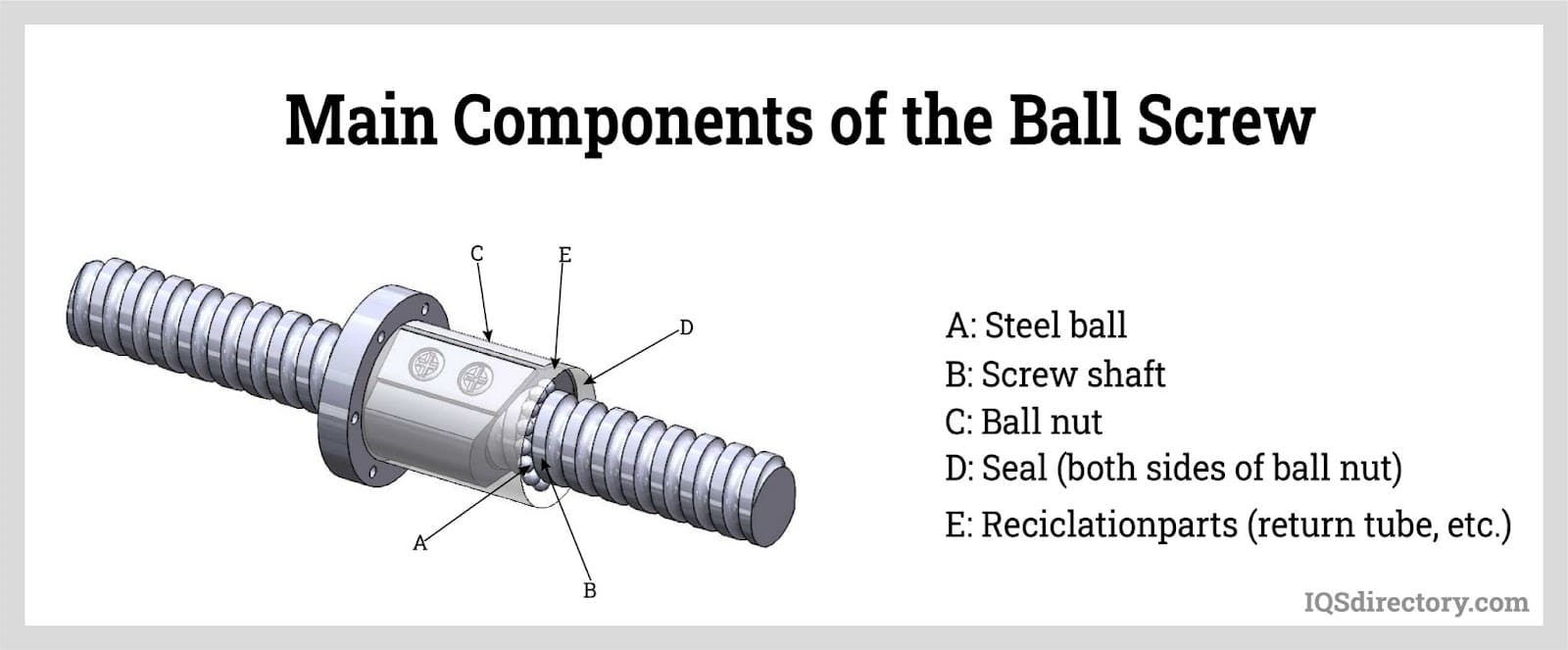
Ball screws are mechanical linear actuators that consist of a screw shaft and a nut that contain a ball that rolls between their matching helical grooves. The primary function of ball screws is to convert rotational motion to linear motion. Ball nuts are used in...
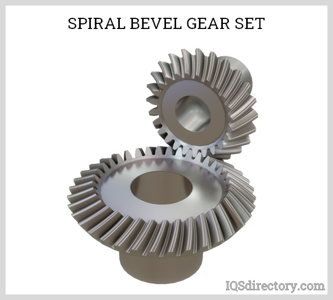
A bevel gear is a toothed rotating machine element used to transfer mechanical energy or shaft power between shafts that are intersecting, either perpendicular or at an angle. This results in a change in the axis of rotation of the shaft power...
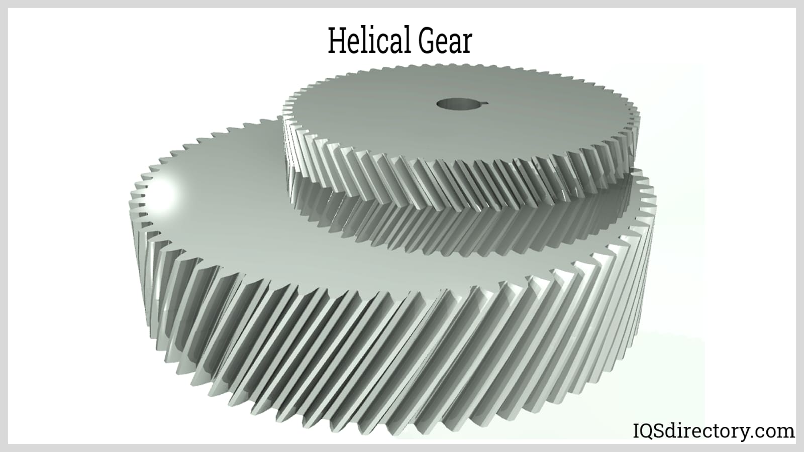
A gear is a particular kind of simple machine that controls the strength or direction of a force. A gear train is made up of multiple gears that are combined and connected by their teeth. These gear trains allow energy to move from...
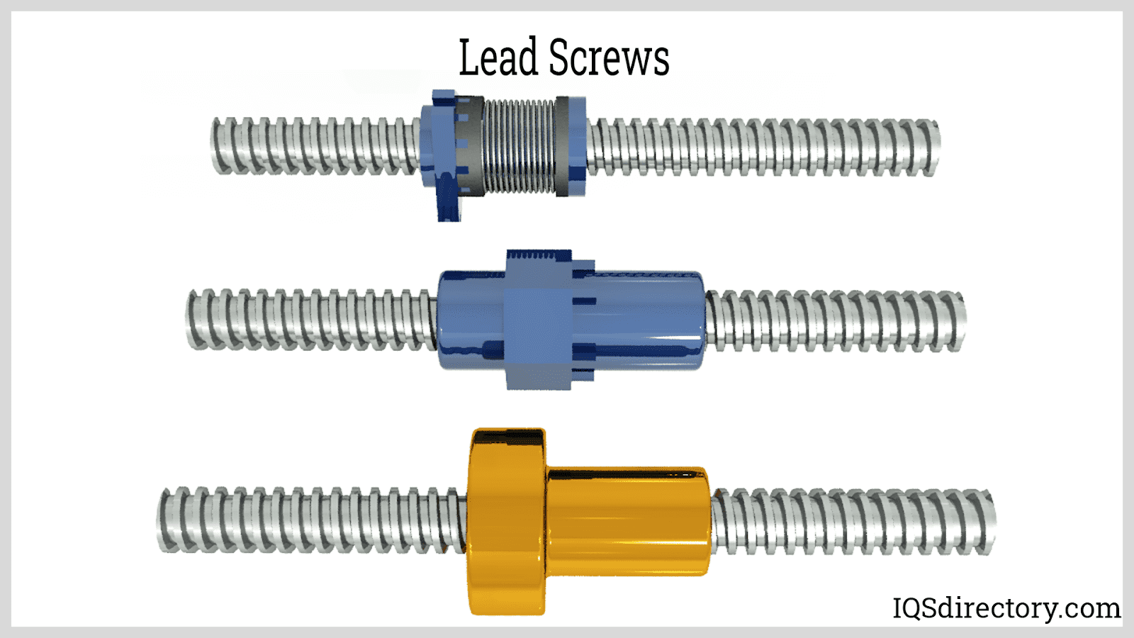
A lead screw is a kind of mechanical linear actuator that converts rotational motion into linear motion. Its operation relies on the sliding of the screw shaft and the nut threads with no ball bearings between them. The screw shaft and the nut are directly moving against each other on...
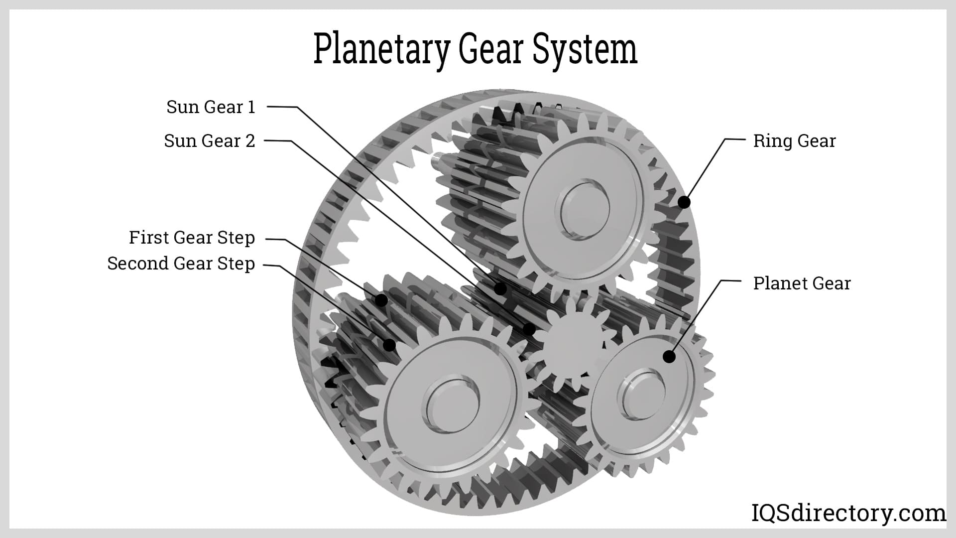
A planetary gear is an epicyclic gear that consists of a central gear, referred to as the sun gear and serves as the input gear, which has three or more gears that rotate around it that are referred to as planets...
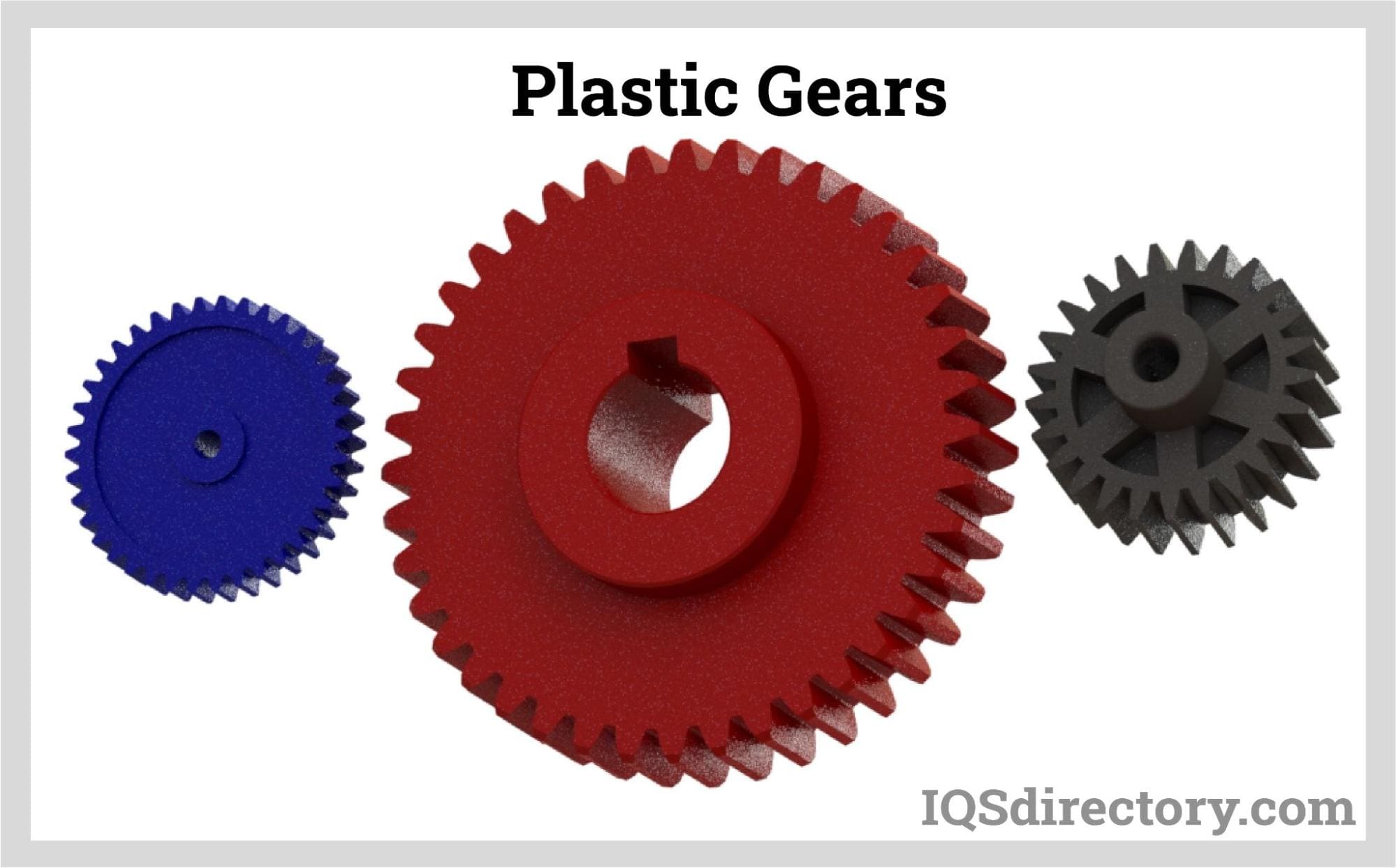
A plastic gear is a toothed wheel made up of engineering plastic materials that work with others to alter the relation between the speed of an engine and the speed of the driven parts. The engineering plastic materials used in manufacturing plastic gears can be...
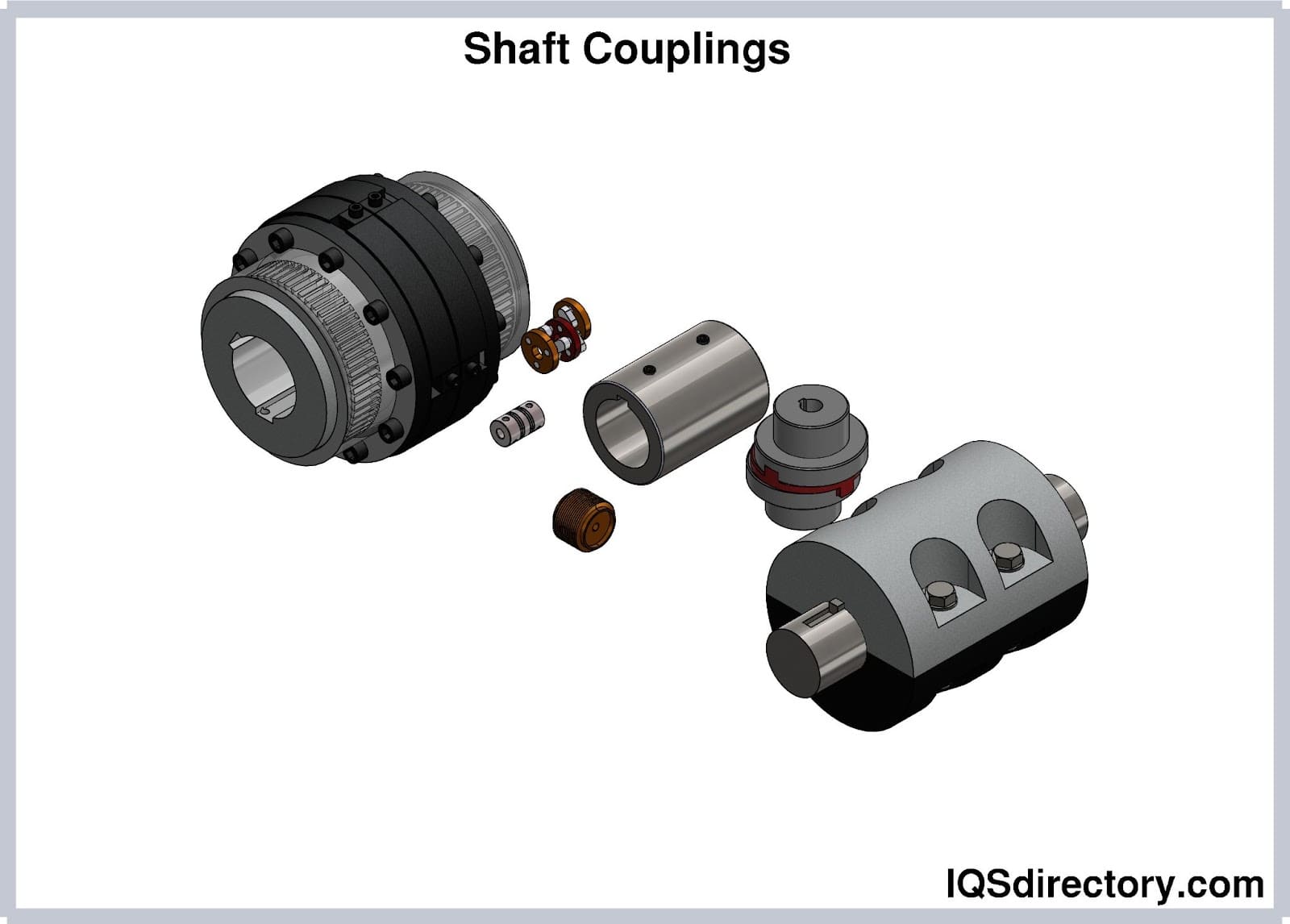
Shaft couplings are devices that connect two shafts to transmit power from the driveshaft to the driven shaft while absorbing some degrees of misalignments and mounting errors between the two shafts...
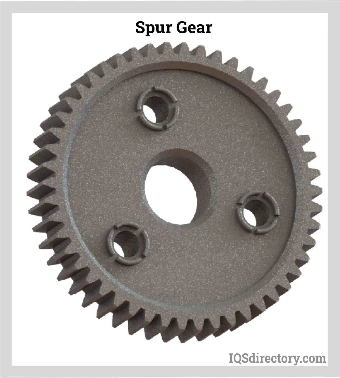
A spur gear is a cylindrical toothed gear with teeth that are parallel to the shaft and is used to transfer mechanical motion and control speed, power, and torque between shafts. They are the most popular types of cylindrical gears and...
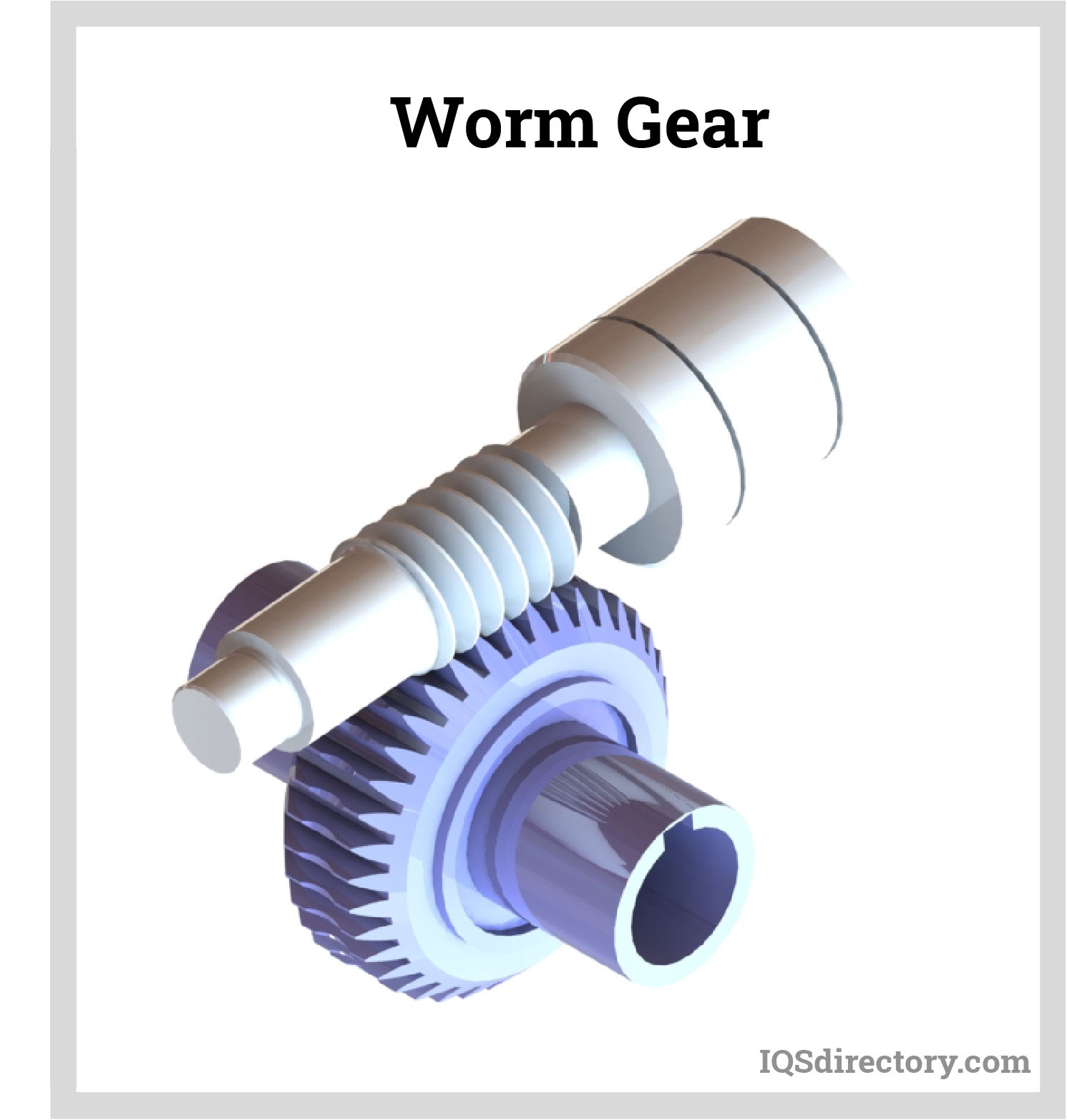
A worm gear is a staggered shaft gear that creates motion between shafts using threads that are cut into a cylindrical bar to provide speed reduction. The combination of a worm wheel and worm are the components of a worm gear...
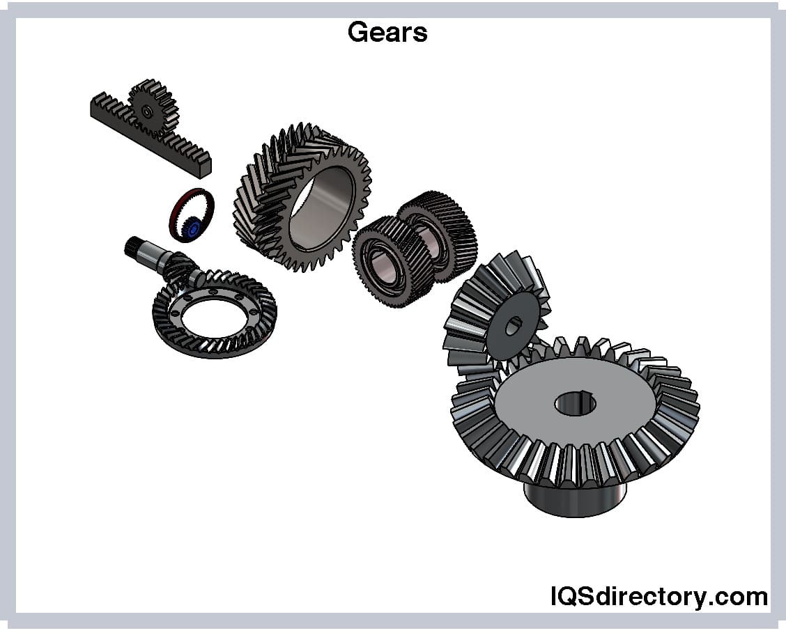
A rotary circular machine with a tooth in its structure and is used to transfer torque and speed from one shaft to another is called a gear. Gears are also known as cogs and have cut teeth in the cogwheel or gear wheel...