Force Sensors
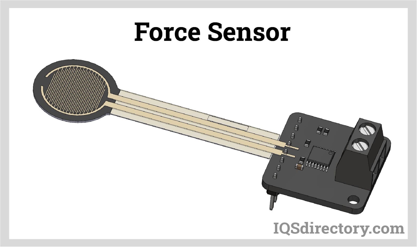
Force sensors are transducers that transform mechanical input forces like weight, tension, compression, torque, strain, stress, or pressure into an electrical output signal whose value can be used to...
Please fill out the following form to submit a Request for Quote to any of the following companies listed on
This article provides comprehensive information regarding load cells and their use.
You will learn:
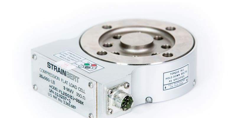
A load cell is a type of transducer that transforms tensile and compressive forces into a measurable electrical output. Typically, load cells are constructed with a spring element and equipped with strain gauges. They are commonly made from robust materials like steel or aluminum, offering strength while maintaining minimal elasticity.
The strain gauge load cell stands as the most prevalent type. Other variations encompass pneumatic and hydraulic load cells. Pneumatic models are ideal for hazardous settings, whereas hydraulic ones are perfect for environments with limited power access. Across all variations, load cells convert mechanical force into digital data, facilitating easy monitoring and recording.
Although the internal structures of load cells can differ depending on their intended use, all are engineered to deliver accurate and precise measurements of mechanical forces or weights. Their categorization is based on measurement precision and load-holding capability.
Diverse kinds of load cells include:
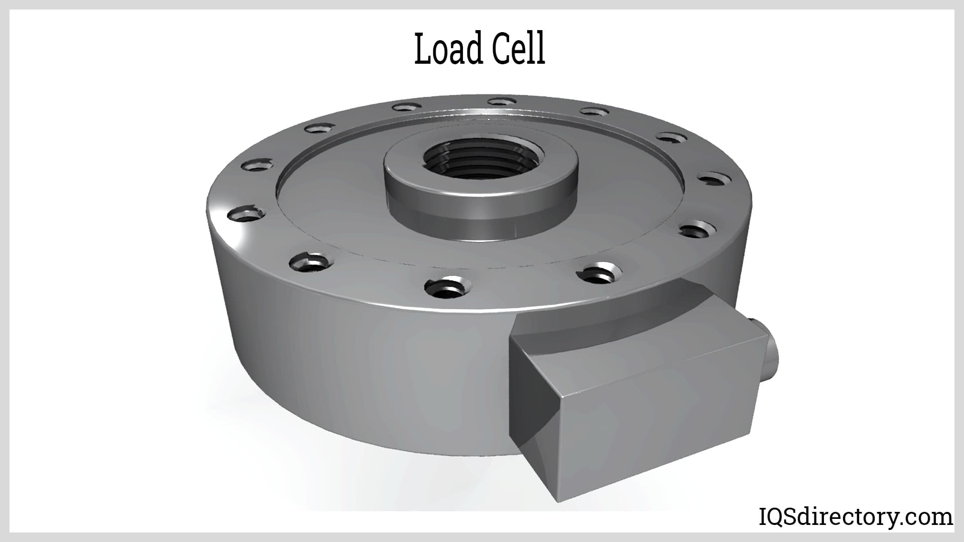
In a load cell, specific areas or structures are engineered to undergo stress when a linear force is applied. These areas detect the applied force and generate an electrical signal proportional to that force. Typically, the output signal is in millivolts and requires amplification to be accurately read and interpreted.
Transducers come in various forms, with strain gauges being the most common and widely used. Other types include capacitive, piezoelectric, vibrating, and magnetic transducers, each employing different principles to provide data.
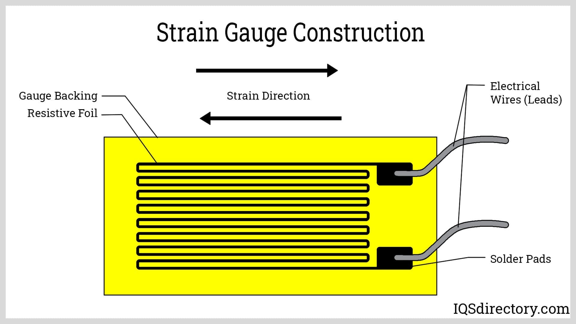
Strain gauge transducers work on the principle of changing electrical resistance as the conductor is being elastically deformed. Tensile stress causes the conductor’s cross section to narrow and elongate as compressive stress widens and shortens it. The amount of stress is converted, transduced, forced, pressured, compressed, torqued, and weight into measurable electrical resistance.
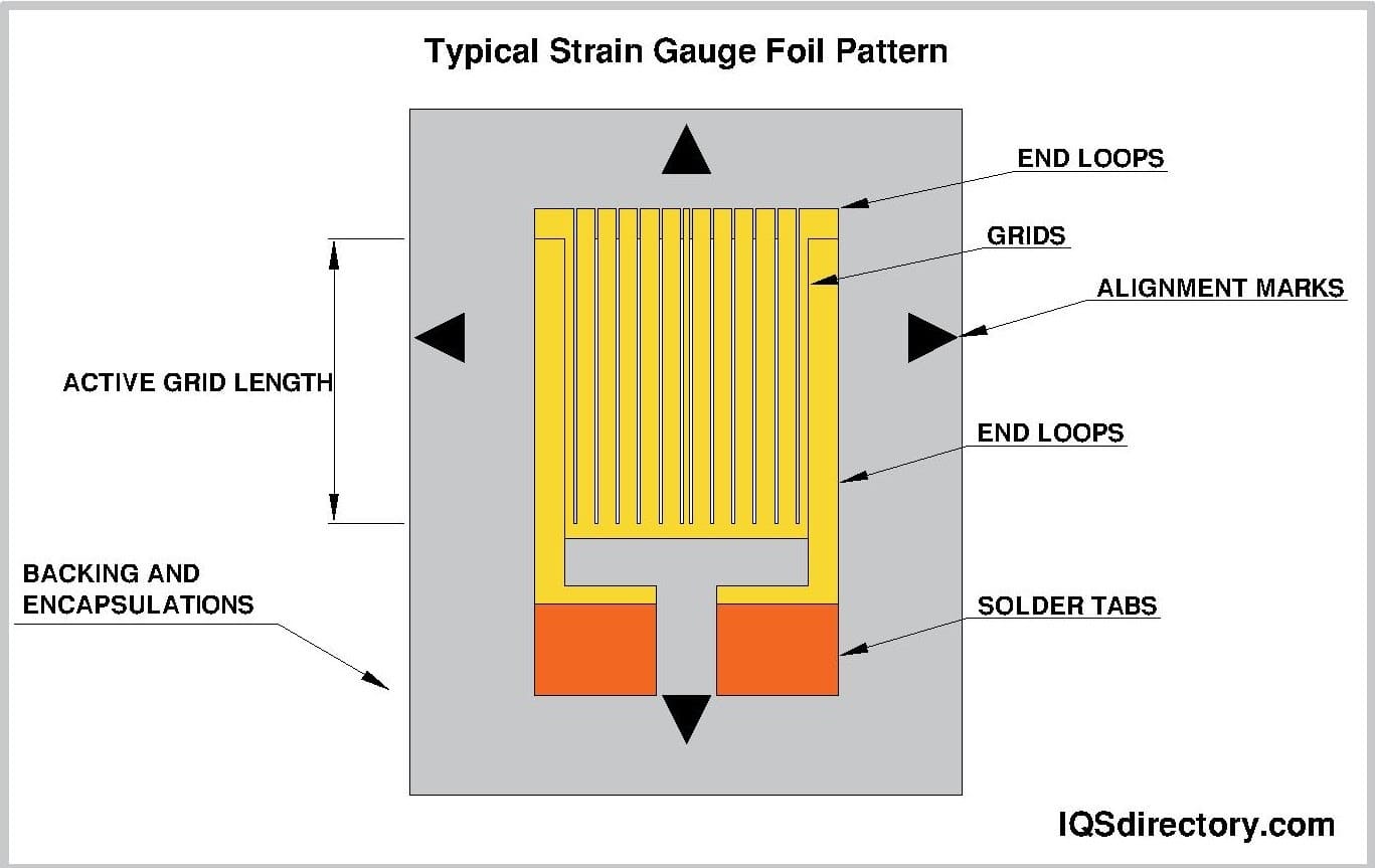
In a load cell, parallel wires are bonded onto the surface of a metal body in a stamp-like pattern. When the body is subjected to stress, the wires deform and resist this stress. The resulting change in resistance is proportional to the applied force, allowing the stress to be measured accurately.
Capacitive force transducers operate by changing capacitance, which is the ability of a system to store electrical charge when a voltage is applied. In parallel plate capacitors, capacitance is directly proportional to the overlap area of the plates and the dielectric material between them, but inversely proportional to the distance separating the plates.
The core principle of a capacitive force transducer relies on the capacitance of a material, which measures its ability to store electric charge. The primary component of the transducer is the capacitor, which can be flat, cylindrical, or spherical, and is also referred to as a capacitive strain gauge.
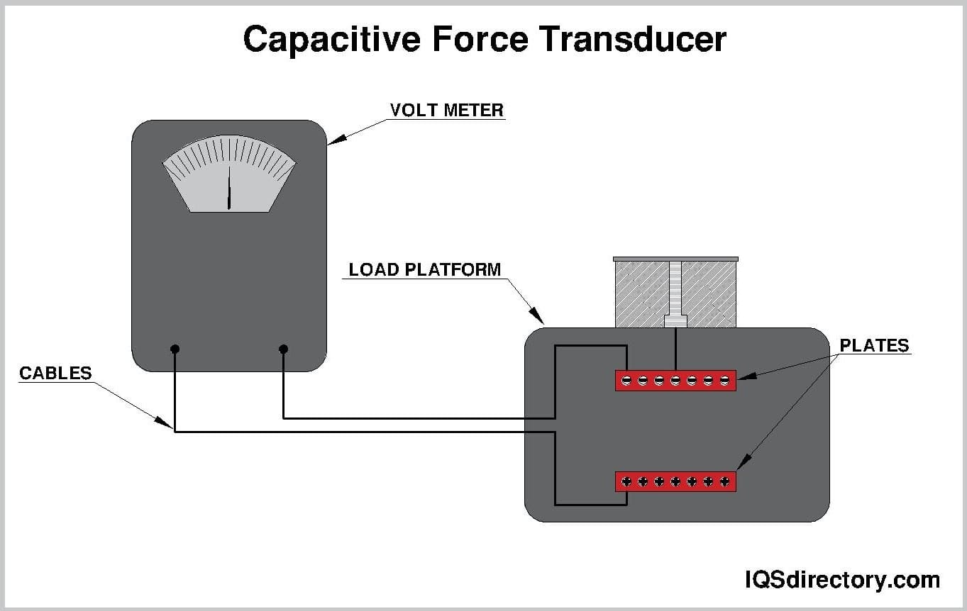
A simple capacitive force transducer consists of two parallel plates separated by an elastic material that also serves as a dielectric. When force is applied across the plates, the dielectric deforms, increasing the capacitance. The capacitance is dependent on both the area of the plates and the distance between them.
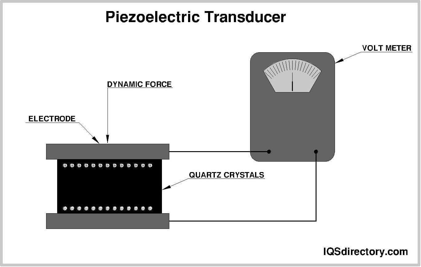
Piezoelectric transducers utilize the piezoelectric effect, which enables certain materials to generate an electric charge when subjected to mechanical stress. These electroacoustic devices convert mechanical stress into electrical signals. The term "piezoelectric" derives from the Greek word for pressure, highlighting their ability to produce electricity under pressure.
When voltage is applied, the elements in a piezoelectric transducer begin to oscillate. They respond almost instantaneously, making them suitable for a variety of applications. Their compact size and broad measuring range facilitate easy handling and installation. Piezoelectric transducers also have a high frequency response, enabling them to detect rapid changes.
Typically, piezoelectric load cells measure forces in a single direction. For measurements in multiple directions, additional transducers may be required. Although piezoelectric transducers generate their own electrical signal, they still need a cable connection for interfacing with other equipment.
Vibrating wire transducers operate based on the principle that the natural frequency of a tensioned wire or string changes with its tension. For a wire of fixed length, mass, and material, increasing the tension results in a higher vibration frequency. The tension in the wire is directly proportional to the square of its vibration frequency.
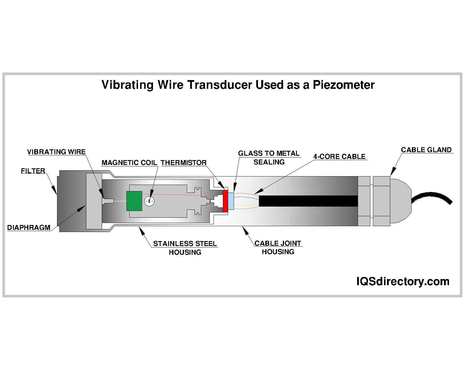
In this type of transducer design, a wire or string is used as the force sensor. An electronic oscillator circuit causes the wire to vibrate at its natural frequency. The wire is attached to a diaphragm where pressure is applied. As the pressure changes on the diaphragm, so is the tension experienced by the wire. The change in tension also changes the wire’s vibration frequency, which is then measured by a sensing coil, which is converted into an electrical signal.
Magnetic transducers, also known as "Pressductor" load cells and developed by ABB, utilize the magneto-elastic effect. This effect involves changes in the permeability of a magnetic core when force is applied. When subjected to mechanical pressure, ferromagnetic elements alter the magnetic moments of their "Weiss" domains. This results in changes in the magnetic characteristics aligned with the direction of the applied forces.
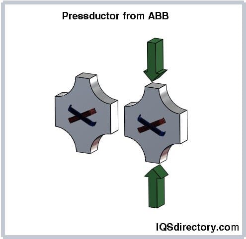
This transducer features a laminated iron core with two perpendicular windings. When an alternating current flows through the primary winding, it generates an alternating magnetic field in the core following the “no load” pattern, where no voltage is induced in the perpendicular secondary winding. Under load conditions, the change in the core's permeability alters the orientation of the magnetic flux lines. This change in orientation creates a magnetic flux that passes through the secondary winding, inducing a voltage. This voltage is then converted into a readable signal.
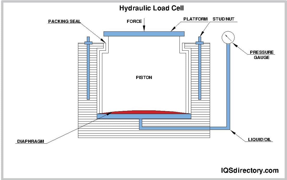
A hydrostatic force transducer comprises a working fluid, a piston or diaphragm, and a cylinder. It measures the pressure between these components and translates it into readable outputs, such as dial readings through a Bourdon tube gauge. This type of transducer includes pneumatic and hydraulic load cells and is ideal for hazardous areas where using an electric load cell with a high ingress protection or ATEX rating would be cost-prohibitive.
The Wheatstone bridge, also known as a resistance bridge, is used to measure an unknown resistance by balancing two legs of a bridge circuit, where one leg has an unknown resistance. The bridge consists of two known resistors, one unknown resistor, and one variable resistor, all connected to form the bridge circuit. It also includes a galvanometer and an electromotive force (EMF) source.
The Wheatstone bridge's four resistors are arranged in a quadrilateral (labeled A, B, C, and D). The EMF source is connected between points A and B, while the galvanometer is connected between points C and D. The current through the galvanometer depends on the voltage difference across it. The bridge is said to be in a balanced condition when the galvanometer shows no deflection, meaning the resistances are set such that the voltage difference across the galvanometer is zero.
In the Wheatstone bridge, the variable resistor acts as the sensing element or strain gauge. Changes in the variable resistor's resistance, relative to the other resistors, result in a current passing through the meter. Essentially, the Wheatstone bridge converts variations in resistance due to strain into a measurable electrical signal, enabling the measurement of unknown resistance.
For strain gauge load cells, the Wheatstone bridge configuration typically involves four strain gauges. All four gauges deform and change resistance when force is applied. The load cell is initially balanced at around 350 ohms with a regulated excitation voltage. When force is applied, the resistance of each strain gauge changes, and these changes are converted into a measurement of weight.
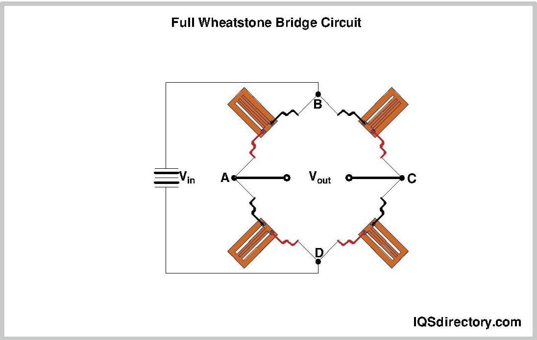
Other Wheatstone bridge designs use two variable resistors to enhance the system's sensitivity and provide a greater voltage variation in response to changing inputs. In a force sensor system, this bridge circuit features two fixed resistors and two variable resistors. A direct current (DC) voltage source powers the circuit. The Wheatstone bridge output, known as the gap voltage measured at Vout, is proportional to the difference in the transducers’ resistance values compared to the reference resistance in the bridge configuration.
This design enables the measurement of very small changes and minimizes the effects of noise on the gap voltage. Fluctuations in the input voltage do not impact the gap voltage since it depends on the ratio of resistances. Additionally, since all resistors are similarly affected, the impact of varying temperatures is effectively canceled out.
Many force transducers use simple elastic elements or a combination of elements, such as pillars, beams, and rings, in their design. When force is applied, these elastic elements deform or deflect. The strain gauge detects this movement, and the Wheatstone bridge converts it into a measurable output.
In tension or compression scenarios, strain gauges are mounted along the length of a cylinder or beam. These gauges are oriented either transversely or longitudinally and connected to a Wheatstone bridge. When the column is compressed, the longitudinal strain gauges experience contraction, while the transverse strain gauges undergo stretching.
A Roberval mechanism is a type of scale featuring two horizontal beams stacked one above the other, each attached to a vertical beam at their ends. This setup is used in strain gauge load cells, which incorporate four thin sections—two on each of the upper and lower beams. One end of the double beam is fixed in a cantilever arrangement, while the other end supports the applied load. Strain gauges are mounted on the top and bottom surfaces near the thin sections of the beams.
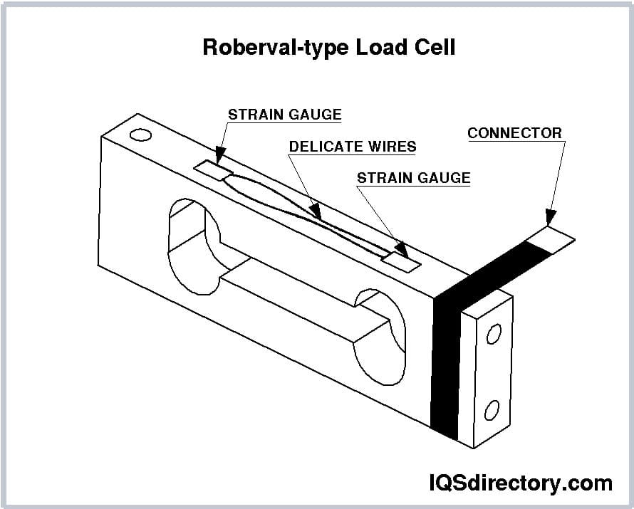
This configuration is ideal for high-precision load cells because all four arms of the Wheatstone bridge are active, resulting in increased sensitivity. When a load is applied, the elastic element deflects, as illustrated in the figure above. In this setup, two strain gauges are placed in tension while the other two are in compression.
In shearing strained elastic elements, strain gauges are oriented at 45° angles relative to the direction of the applied load. This arrangement allows for accurate load measurement regardless of the load's application point. The bending strain experienced by the strain gauges is effectively canceled out because half of each strain gauge undergoes bending strain in one direction, while the other half experiences an equal magnitude of strain in the opposite direction.
Shearing strained elastic elements can be further classified as:
These elastic elements can be made from various materials, with alloy steel, aluminum, and stainless steel being the most common. Alloy steels are often chosen for their cost-effectiveness, with AISI 4330 being particularly popular. This medium carbon, low-alloy steel contains chromium, nickel, and molybdenum, offering good hardenability, high transverse strength, and toughness.
Aluminum is typically used in single-point, low-capacity applications. Its main advantage is its low cost, making it the least expensive of the three materials. Aluminum alloy 2023 is favored for its low creep and hysteresis characteristics.
Stainless steel is preferred for applications involving moisture or corrosive environments. Although generally more expensive than alloy steels, stainless steel offers superior corrosion resistance. Alloy 17-4PH, or AISI 630, a martensitic chromium-nickel stainless steel stabilized with niobium, is commonly used. It combines corrosion resistance with high strength and toughness.
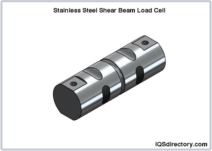
Load cells can also be classified according to their outer shape. Each shape has specific applications and may be used individually or in combination with other elastic elements.
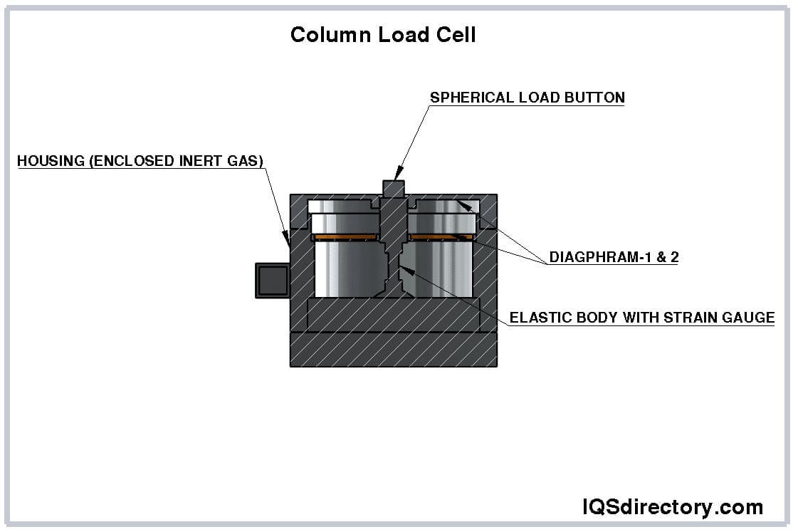
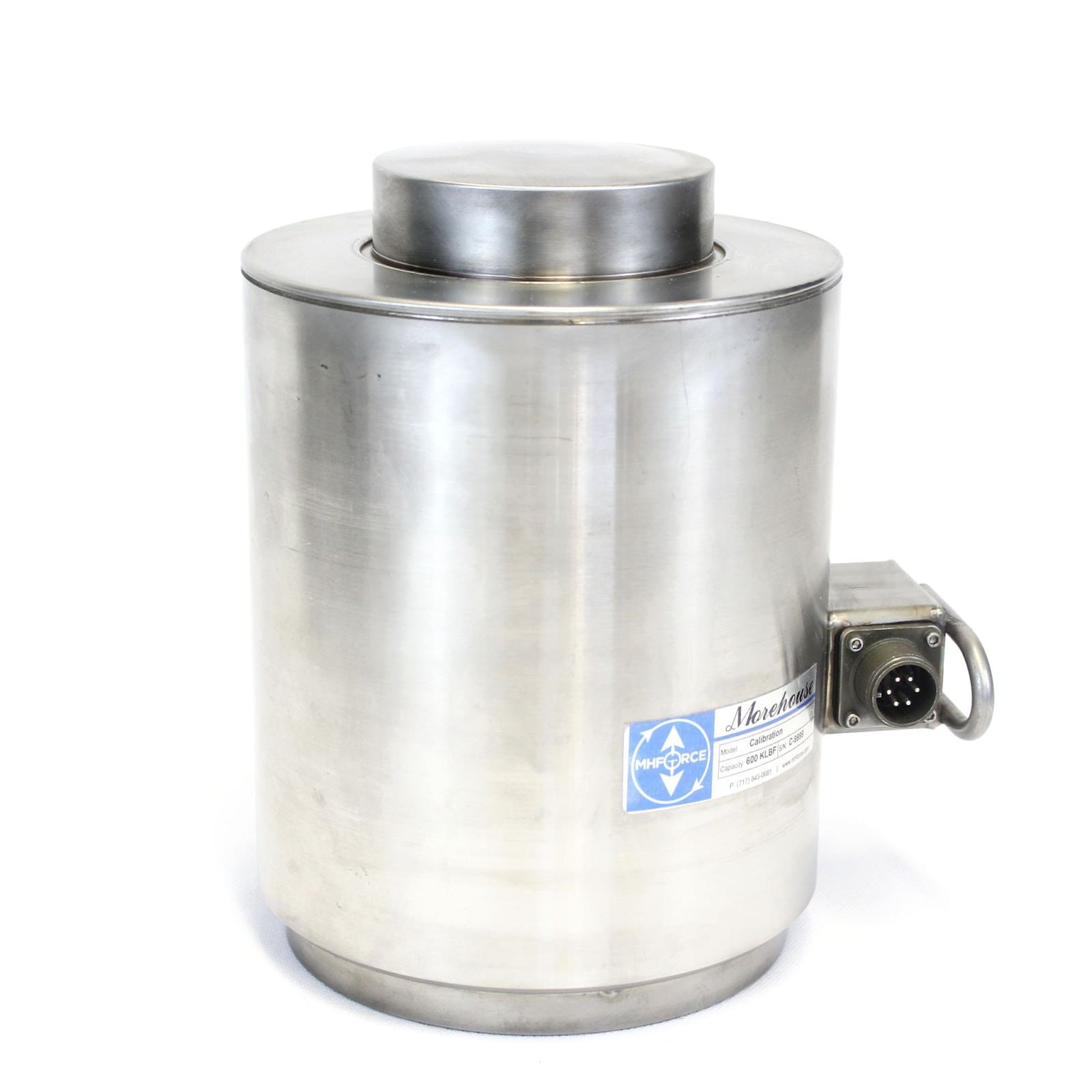
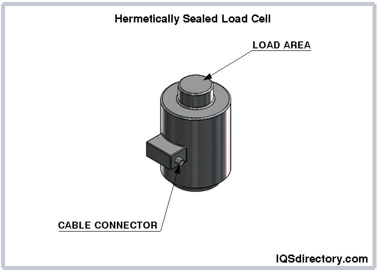
Canister load cells are among the earliest designs of load cells. They feature a single or multiple columns that are either stretched or compressed and are hermetically sealed to protect the strain gauges. Canister load cells can handle capacities ranging from 100 lbs to 500,000 lbs, depending on the number of columns. They are designed to measure either tension or compression but are limited in their ability to withstand side loads.
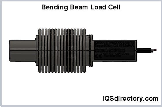
At first glance, bending beam load cells might seem similar to shear beam load cells, but they differ in their elastic elements. Unlike shear beams, bending beam load cells do not feature a reduced cross-section for strain gauges. Instead, they have a beam that is machined all the way through, with strain gauges bonded to the beam in a manner similar to that seen in Roberval-type load cells.
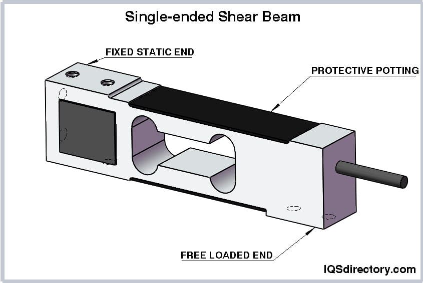
Single-ended shear beam load cells utilize an "I"-profile shear beam design. In this setup, the elastic element, made from spring material, features a reduced cross-section where strain gauges are bonded. One end of the shear beam is equipped with mounting holes, while the load is applied at the other end. These load cells are commonly used in low-profile scale applications.
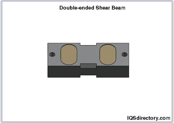
The double-ended shear beam load cell resembles the single-ended shear beam design but with a key difference. Instead of being fixed at one end with the load applied to the other, the double-ended shear beam is secured at both ends, with the load applied to the center of the load cell.
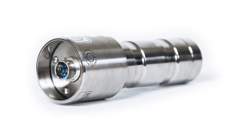
Load measuring pins or bolts are designed to measure tension and have a rod-like shape. They consist of short, thick-walled tubes with strain gauges mounted on each side of the center section at 45° angles to the tube's axis. These pins or bolts also feature a spring element that applies a perpendicular force to the horizontal axis. Typically, load measuring pins or bolts are installed in machinery in place of standard shafts, seamlessly integrating into the assembly as a normal component.
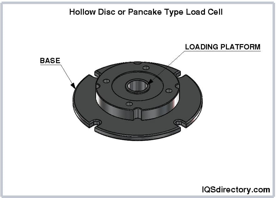
These are hollow disc load cells featuring a circular array of holes situated about halfway from the center to the edge of the disc. Shear strain gauges are installed within these holes at 45° angles relative to the loading axis. With their very low profile, these load cells can be mounted between components for compression applications or used in tension. Force is applied to the center of the cell, where the beam arms converge.
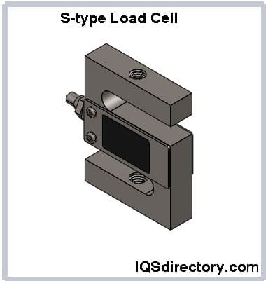
These load cells feature an elastic element that deforms under tension or compression at both ends. The strain gauges are typically arranged in an “X”-pattern. S-type load cells are compact, cost-effective, monolithic, and straightforward to install. They are commonly used in tension applications and are often found in hanging scales or other suspended weighing systems. S-type load cells can be suspended from shackles or mounted between components using eye bolts at their top and bottom.
These load cells operate based on the principle of a wire wound spring. The helical wire converts the applied load into a torsional moment. This design is particularly resistant to off-axis loading because the torsional moment propagates uniformly through the helix, making the orientation of the strain gauge less critical.
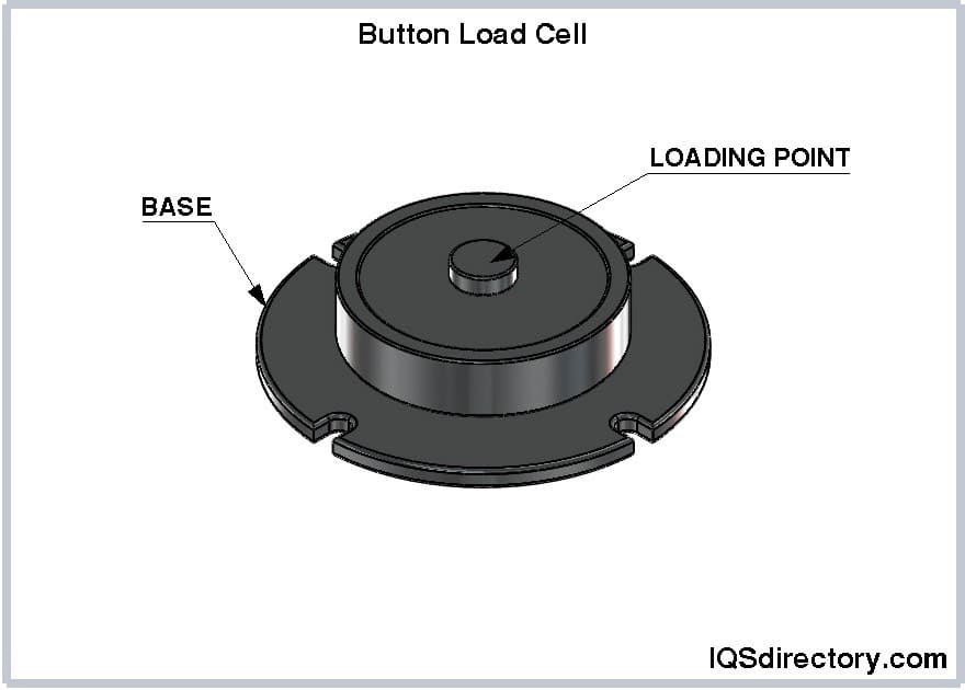
The elastic element is usually a bent ring, bent membrane, or a diaphragm depending on the manufacturer’s design, but it uses the principle of bending beam elastic elements. These load cells have a low profile enabling them to be used in a variety of applications. However, they can only measure compression. The low profile of button load cells causes them to be referred to as a miniature load cell.
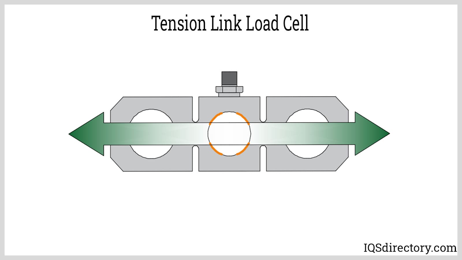
Tension link load cells are versatile and can be customized for various load capacities, from low to high. They are commonly used in crane and hoist scales, pull testing, and tensile strength measurement. Featuring a figure-8 shape, tension link load cells can be connected between cables, ropes, or chains. The loading axis is vertical, and the strain gauges are arranged parallel to each other to accurately measure the loading strain.
Load cells are classified based on their output signal or method of weight detection. Their primary function is to measure force, convert these measurements into digital values, and transmit the data in various formats for reading and recording. The importance of load cells lies in their simple design coupled with the complex algorithms they use to deliver accurate weight and force data.
Hydraulic load cells measure weight by detecting changes in pressure within an internal fluid. In a diaphragm hydraulic force sensor, the applied load compresses fluid in a sealed elastomeric diaphragm chamber via a piston. As the load increases, the pressure in the fluid rises correspondingly. The output of hydraulic load cells is linear and remains consistent regardless of the fluid quantity or its temperature.

Pneumatic load cells operate on the principle of force balance and utilize multiple dampening chambers to achieve highly accurate measurements. They feature an elastic diaphragm attached to a platform surface. When an object is placed on the load cell, pressurized air or gas is used to counterbalance its weight. The amount of air required to achieve this balance directly corresponds to the object's weight.
Pneumatic load cells are ideal for industries where precise measurement of small weights is crucial and where cleanliness and safety are priorities. They are explosion-proof, unaffected by temperature fluctuations, and free of fluids that could contaminate processes in the event of a diaphragm rupture.
Strain gauge load cells are the most widely used type of load cell, with capacities ranging from 5 N to over 50 MN. They feature high-resolution digital indicators and adhere to optimal force transfer standards. Strain gauge load cells function as transducers that alter electrical resistance when subjected to stress or strain, with resistance changes proportional to the strain experienced by the cell. The measurements from strain gauge load cells are linear and can be converted into force and weight readings.
Miniature load cells are compression load cells engineered for high-capacity applications in confined spaces. They come in miniature or subminiature sizes, typically with diameters of 51 mm (2 inches) or less. Their compact size makes them suitable for test benches, industrial weighing, and prototypes. Miniature load cells feature twist-lock connectors and cable connections, with metric configurations ranging from 0 to 100 N up to 0 to 50,000 N.
Donut load cells, also known as thru-hole load cells, are designed to measure compressive forces and are named for their distinctive shape. They are round and smooth, featuring a central hole that allows parts or bolts to pass through. Commonly used in oil and gas pumps, donut load cells are ideal for applications where the load structure needs to pass through the load cell. Available in both tension and compression models, they can measure loads ranging from 150 g to 100 tons. Donut load cells are utilized for measuring bolt forces, clamping forces, monitoring overloads, and overseeing rolling mill systems.
Capacitive load cells measure force using capacitance, which is the ability to store an electrical charge. These load cells consist of two flat, parallel plates. When current is applied, it is stored between the plates, and the capacitance, or the amount of stored charge, indicates the distance between the plates. As a load is applied, the distance between the plates decreases, and this change can be converted into a weight measurement.
Capacitive load cells are typically classified into two types: low and mid-range.
Micro load cells are resistive load cells that operate based on the principle of zero piezoresistivity. When a load, force, or stress is applied to the sensor, the resistance changes, which in turn alters the output voltage due to variations in the input voltage. These load cells are designed for compression force measurements in confined spaces where precision and durability are essential. They can handle weights ranging from 10 g to 1 ton and are available in heights as low as 3.3 mm, with a maximum height of 10 mm.
Multi-axis load cells are designed to measure forces and torques in multiple directions, often capturing up to six different components. They are particularly useful for measuring multidimensional loads along the x, y, and z axes, or three spatial directions, and convert these measurements into electrical output signals. Multi-axis load cells are commonly employed in robotics and for machine monitoring to enforce load limits.
While it is possible to use multiple load cells to measure force and torque in various applications, multi-axis load cells consolidate these functions into a single device. They are engineered to simultaneously measure a range of forces using one load cell, simplifying the measurement process.
Multi-axis load cells feature multiple bridges that precisely measure force in a specific direction with minimal cross-talk from other forces or moments. They combine the benefits of simultaneous measurement, compact design, and reduced error. These load cells are selected for their force range, accuracy, ease of mounting, and durability under various environmental conditions.
In contrast to single-point load cells, multi-axis load cells can measure tension, compression, and torque in all directions. Equipped with multiple strain gauge bridges, they measure forces and torque in one direction while minimizing interference from forces applied in other directions. This capability allows for space-saving in assembly and reduces installation time.
Multi-column load cells feature four or more small columns, each equipped with its own strain gauge, which are connected in series within the bridge arms. Similar to multi-axis load cells, multi-column load cells are more compact than high-stress column load cells. They offer improved discrimination of off-axis load components and exhibit reduced creep. Designed with a shear web spring, multi-column load cells provide enhanced output, linearity, lower hysteresis, and faster response times.
While multi-column load cells are heavier, limiting their use for lightweight applications, they offer exceptional accuracy, typically within 0.0125% of full scale. They are known for their high capacity, ranging from 100,000 lbf to 2.25 million lbf (or up to 10 MN). Multi-column load cells can be combined, such as with a 50,000 lbf load cell and a 1,000 lbf load cell, to cover a measurement range from 40 lbf up to 600,000 lbf.
High-capacity load cells are designed to measure extremely large loads, such as those exerted by mining equipment or rocket thrust forces. They are integrated into various machines, systems, and instruments, and are characterized by their small size, lightweight, and compact design. Custom-designed to meet the specific requirements of each application, high-capacity load cells may need to be integrated into existing mechanisms.
Dynamometer load cells, or dynos, are used to measure force, torque, and power. When integrated with load cell sensing technology, these dynamometers measure engine power output with high precision. They also offer extremely accurate measurements for cabling and wiring installations, enhancing safety. Dynamometer load cells are designed to handle loads of several tons.
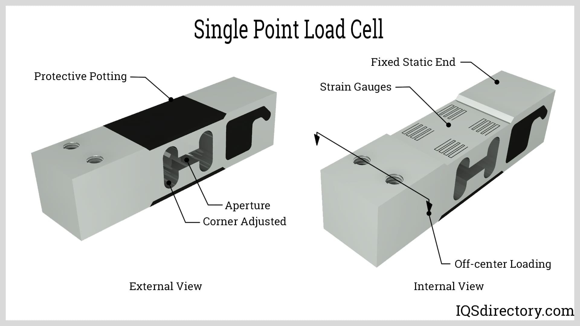
Single-point load cells are designed for individual device applications, such as supermarket scales, and feature a single load cell. To ensure accurate readings, the load must be properly aligned, given the design of these load cells. They are frequently used with platform scales. Single-point load cells come in a wide range of shapes and sizes to suit various applications, and their unique characteristic is the inner aperture—a cutout in the load cell's body that distinguishes them from other types.
S-beam load cells are bending beam load cells designed for weighing applications with capacities up to 50 lbs (22 kg). They feature a metal spring element that deforms under the application of force or weight. The strain gauge measures the fractional change in deformation length. S-beam load cells are commonly used in scales and tension measurement applications.
Popular for their precision, affordability, and ease of installation, S-beam load cells are intended for inline applications. They are sensitive to external loads and torque, requiring careful centering and proper alignment to ensure accurate measurements.
Inline load cells are designed to be installed along the load axis for tension measurement and come with various thread configurations. They are built to withstand off-axis loads, making them ideal for applications where side loading is unavoidable. Their compact design allows them to fit into existing systems with tight spacing or clearance. The durability and reliability of inline load cells contribute to their widespread use.
These load cells often feature temperature compensation to ensure excellent performance. They can measure tensile and compressive loads up to 5000 N with ±0.25% non-linearity. Inline load cells are bi-directional and offer compact construction for long-term stability. They are commonly used in the automotive industry and robotics for precise force sensing.
Load Pins, known as clevis pins or dynamometric axles, are a type of weight sensor used for overhead equipment. They have rod shaped elements and are short, thick-walled tubes with strain gauges bonded on each side of the center section at 45° angles with respect to the tube axis. A spring element applies perpendicular force to the horizontal axis and measures the acting force. Load pins are typically installed into machines in place of normal shafts and act like a normal piece of the assembly.
The strain limitations on a shaft are crucial in determining the design requirements for load pins, particularly where they make contact with the holding plate. These contact areas are typically thinner than the central section of the tool. Force load pins are designed to handle strain ranges from 150 N/mm² to 200 N/mm², while hoist load pins accommodate strains from 100 N/mm² to 120 N/mm². Among force, hoist, and lift load pins, lift load pins have the lowest strain limit at 50 N/mm². These design considerations are essential to ensure the mechanical integrity and fatigue resistance of both the load pin and its mounting.
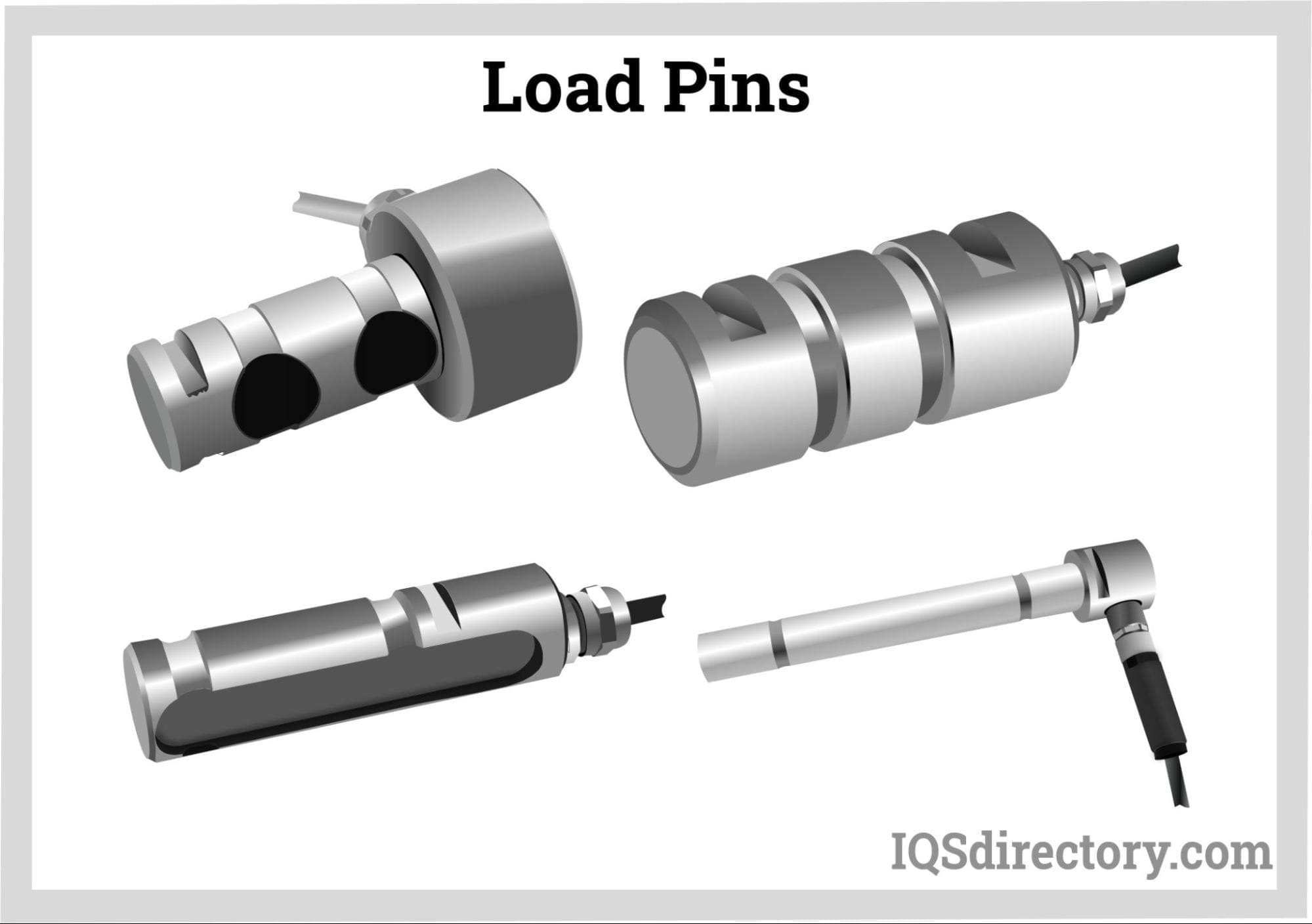
The load pin's measurement area is defined by two grooves situated between the forces applied externally. The pressure exerted by the fixed support counteracts the pressure from the lug or sheave. Load pins measure force or pressure and transmit these measurements to a weight display. They continuously monitor the load, enhance safety, and prevent overload damage. Constructed from corrosion-resistant stainless steel, load pins are designed for internal placement within systems.
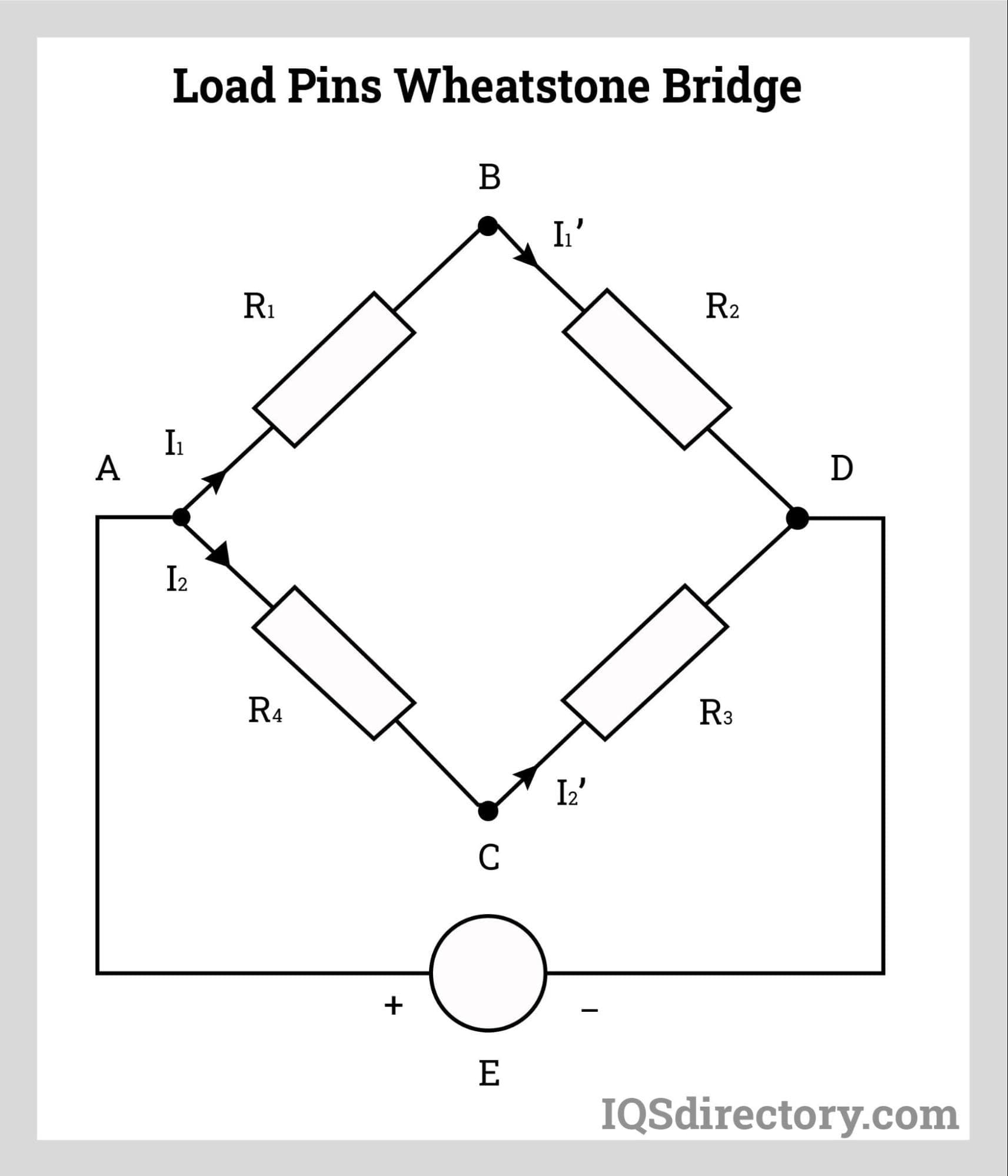
Load pins are strain gauges with a Wheatstone bridge circuit that generates variable output voltage proportional to the force acting on the elastic element when activated by a fixed voltage source. As a result, the mechanical input quantity is changed into electrical output.
Load pins are made of high-strength alloy steel or stainless steel, which makes it possible to use them in hostile corrosive environments. They are simple to install and are a cost effective method for load measuring. Load pins are available with thermal compensation and electronic wireless transmitters for monitoring.
To ensure accurate measurements, a load pin must be rated appropriately for the weight it will measure. If the load pin's capacity is too high, it may not provide precise data. The sensitivity of a load pin is affected by its mounting, the span of the mounting, and the hardness of the material holding it. Load pin diameters range from 7 mm to 480 mm, with capacities spanning from 2000 N to 30 MN. Higher capacities can be manufactured but require specialized planning.
Additional factors influencing the use of a load pin include its installation location, necessary certifications, and the types of materials it will encounter—such as liquids, gases, or solids—which affect its ingress protection (IP) rating. Temperature variations, vibrations, airflow, and wind must also be considered to ensure accurate measurements and equipment durability.
Load pins are equipped with signal amplifiers that support various output formats, including mV/V, 4-20 mA, 0-10 V (and derived), RS485, Modbus, and CAN. Analog amplifiers can be adjusted to handle overloads without signal saturation, accommodating a range from "0" to nominal capacity or other specified limits.
A load pin's primary purpose is to measure force or weight by using a sensor that converts the applied force into an electrical signal. It features a small internal bore machined along its neutral axis to safeguard the internal instrumentation from external conditions. The functionality and application of load pins have significantly expanded over the years, as they can be custom-engineered to suit a wide range of applications.
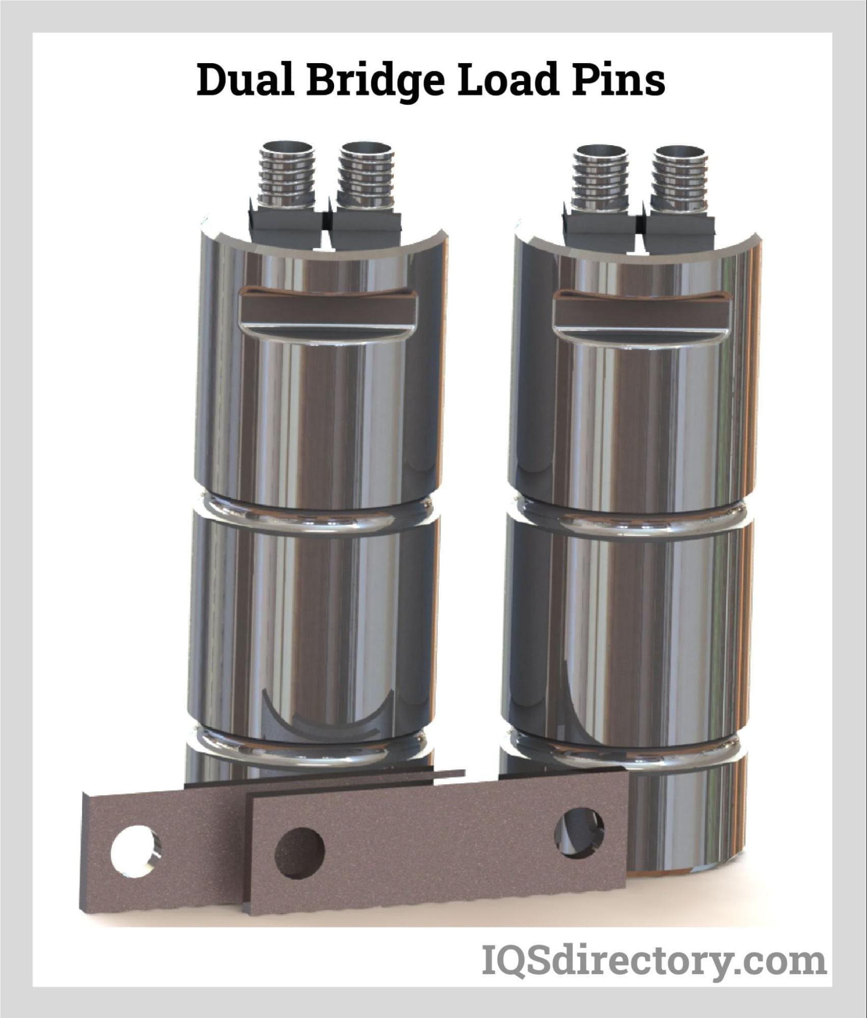
Twin bridge clevis pins offer two independent strain gauge circuits. These dual bridge transducers can use one bridge for measurement while reserving the other as a backup, or they can operate both bridges simultaneously for both control and measurement purposes.
Electrical terminations can be configured with either single or dual connectors and may be radial or axial. Additionally, cables can be permanently attached if preferred.
Wireless load pins are ideal for situations where cable installation is difficult or costly. They offer long battery life and deliver precise measurements with excellent resolution and stability. These load pins feature a straightforward setup, calibration, data logging, and recording interface. They have a transmission range of up to 800 meters (2600 feet) and are compatible with specialized clevis pins.
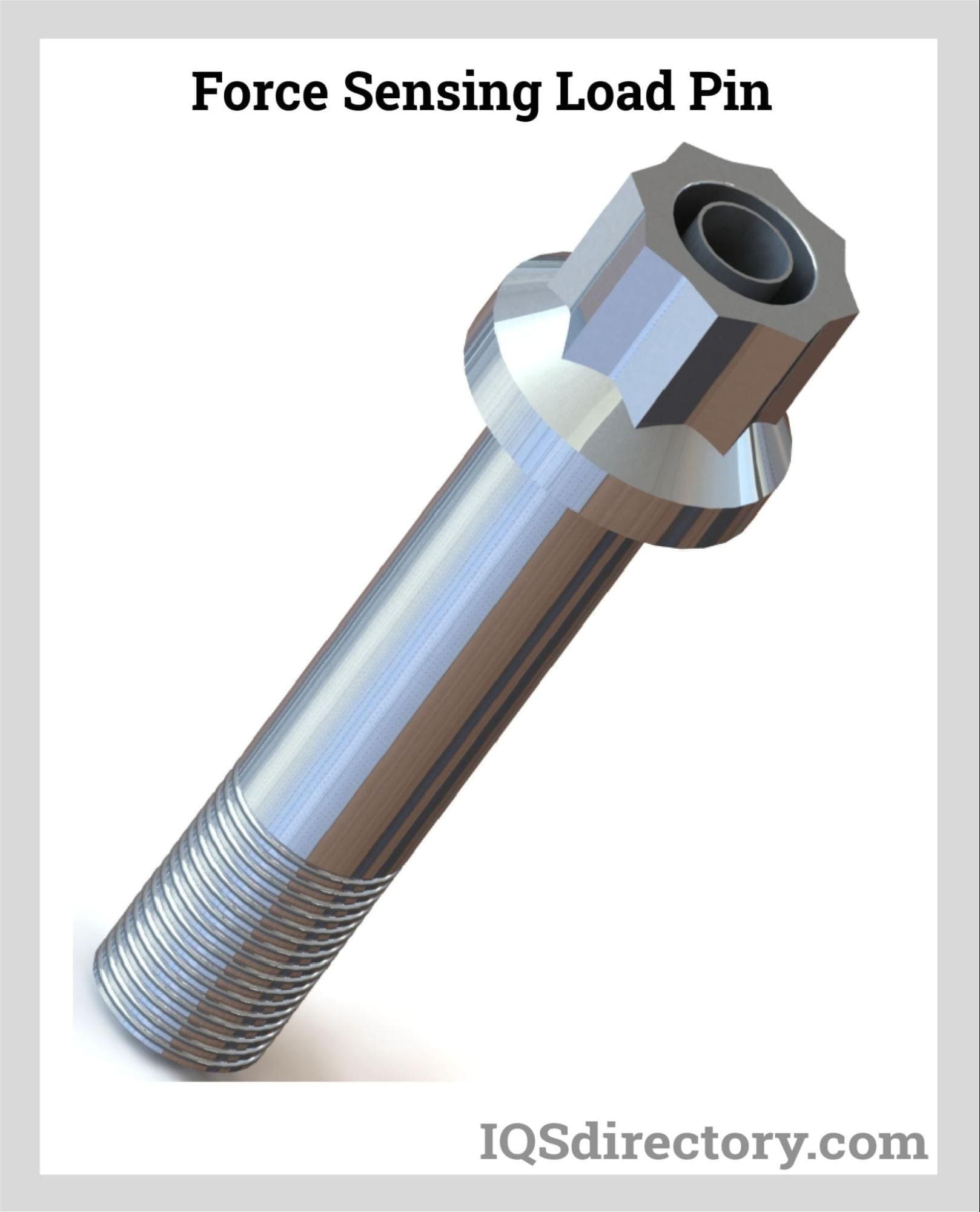
Force-sensitive load pins, also known as clevis pins or clevis bolts, are load sensors that incorporate an internal strain gauge transducer along with flat load cells and tension links. Strain gauges are mounted at the interfaces between the clevis and the clevis eye and are sealed within axial holes in the load pin. Positioned in a neutral plane in one direction, the load pin can detect strains resulting from shear stresses at two distinct sections.
Each load pin features four strain gauges—two at each location—electrically connected to form a full bridge. Since the signals from each strain gauge are additive, the bridge's output is proportional to the total loads measured by the shear planes of the pin. The circuit often includes temperature compensation, signal trimming, and balancing resistors, which are connected via suitable connector sockets or integral cables.
Standard force-sensing load pins and bolts are calibrated to handle loads up to 500,000 lbs. They typically require higher capacity calibration data. While calibrations are generally designed to replicate installed conditions, it is recommended to perform in-place calibration to account for installation, tolerance, and alignment effects that may influence sensor data.
A specialized type of force-sensitive load pin is the standard wire rope load pin, used with cranes, marine mooring lines, and hoists. These load pins replace clevis pins in wire rope socket hardware and share the same structure as other force-sensitive load pins, providing high-capacity calibration data. Additionally, shackle load bolts or pins are used in conjunction with wire rope load pins for applications involving Crosby anchors and chain shackles.
Sheave and pulley systems employ various load pin designs that can be integrated around a clevis pin or used with an existing sheave. These load pins are crucial for measuring line tension. An important consideration in using sheave and pulley load pins is the wrap angle, which can be either variable or constant. This angle determines whether the system will utilize one or two strain gauge bridges to measure the load accurately.
As durable and resilient as load pins are, they are susceptible to various factors that can influence their readings. Regular Calibration, at intervals, is required to ensure a load pin is operating within its specifications, since all load pins experience degradation through usage, abuse, drift, or aging. Electrical impact, mechanical effects, instrumentation errors, and loose wires reduce load pin performance and reliability over time. Particulate matter can also accumulate that can cause failure if a load pin is not properly cleaned, which can lead to operational problems. Load pin manufacturers strongly advise that regular maintenance be performed on load pins to ensure accurate readings.
Force sensors are transducers that convert mechanical forces—such as weight, tension, compression, torque, strain, stress, or pressure—into an electrical output signal. This signal represents the magnitude of the force and can be used to notify operators or serve as inputs for controlling machinery and processes. The output signals may be sent to indicators, controllers, or computers.
The core principle of force sensors is their response to applied forces, which they convert into measurable data. Typically, force sensors include electrodes and sensing materials. By measuring the resistance encountered by the force sensing resistors, which are key components of these sensors, the amount of force applied can be determined.
Force sensing resistors operate based on the property of contact resistance. In these sensors, a conductive polymer sheet changes its resistance when force is applied to its surface. The polymer sheets are embedded with a matrix of sub-micrometer-sized electrically conductive and non-conductive particles.
When force is applied, these micro-sized particles in the polymer sheet make contact with the sensor electrodes, altering the resistance of the film. The extent of this resistance change provides a measure of the applied force, which can be quantified in terms of mechanical force or pressure.

Load cells are essential in industrial and manufacturing plants for accurately measuring quantities of raw materials and finished products. They play a crucial role along the process line, helping to monitor material levels and adjust process parameters as needed. Load cells are commonly used in various industrial equipment, including hoppers, silos, tanks, conveyors, and packaging machines.
A prominent example of equipment that utilizes load cells is the universal testing machine. Laboratory scales also rely on load cells for highly precise measurements. However, it's important to note that other principles of force transduction, aside from strain gauges, are also employed in various applications.
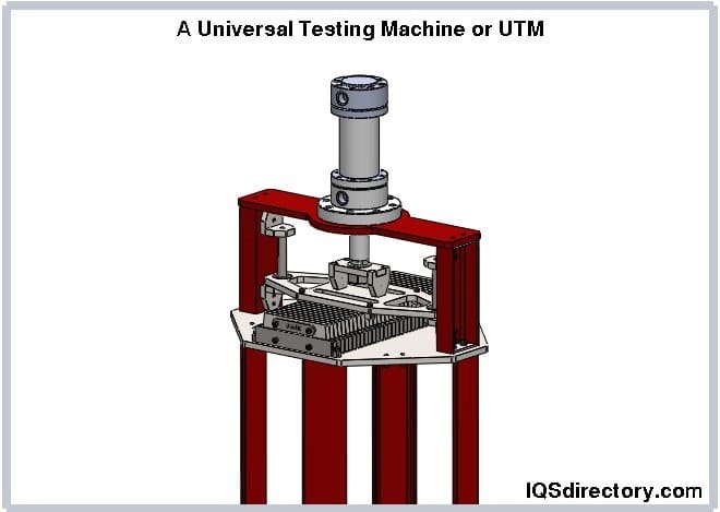
Load cells provide output signals that can serve as feedback for process line automation. They are integral to systems for automatic packaging, distribution, and sorting.
Load cells are also employed in truck platforms, weighbridges, cranes, and railways. In these applications, they primarily measure the weight of goods loaded onto trucks and containers.
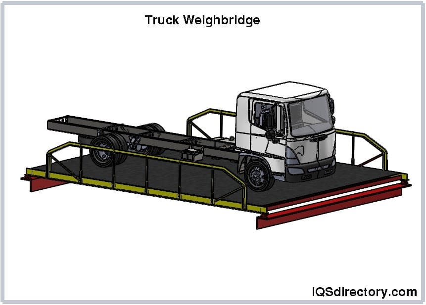
Force sensors are available in a wide range of sizes and shapes. Their three fundamental parts are force sensitive components that change when stress or force is applied, a conversion component to produce measurable units, and a circuit. Typically formed of enameled wire or PCB board with force sensitive components, the circuit is composed of aluminum alloy, alloy steel, and stainless steel. It is created by connecting gauges across the sensing element. The conversion element is a strain gauge made of a coil or can be a piezoelectric sensor that runs on a crystal.
Force sensor outputs can include analog voltage, analog current, analog frequency, switches or alarms, and serial or parallel signals. Measuring circuits often use four gauges, though more complex sensors can incorporate up to thirty gauges. The sensitivity of a force sensor to detect and track measurement deviations improves with the number of gauges, and the Wheatstone bridge equation is used to design these gauges and circuits.
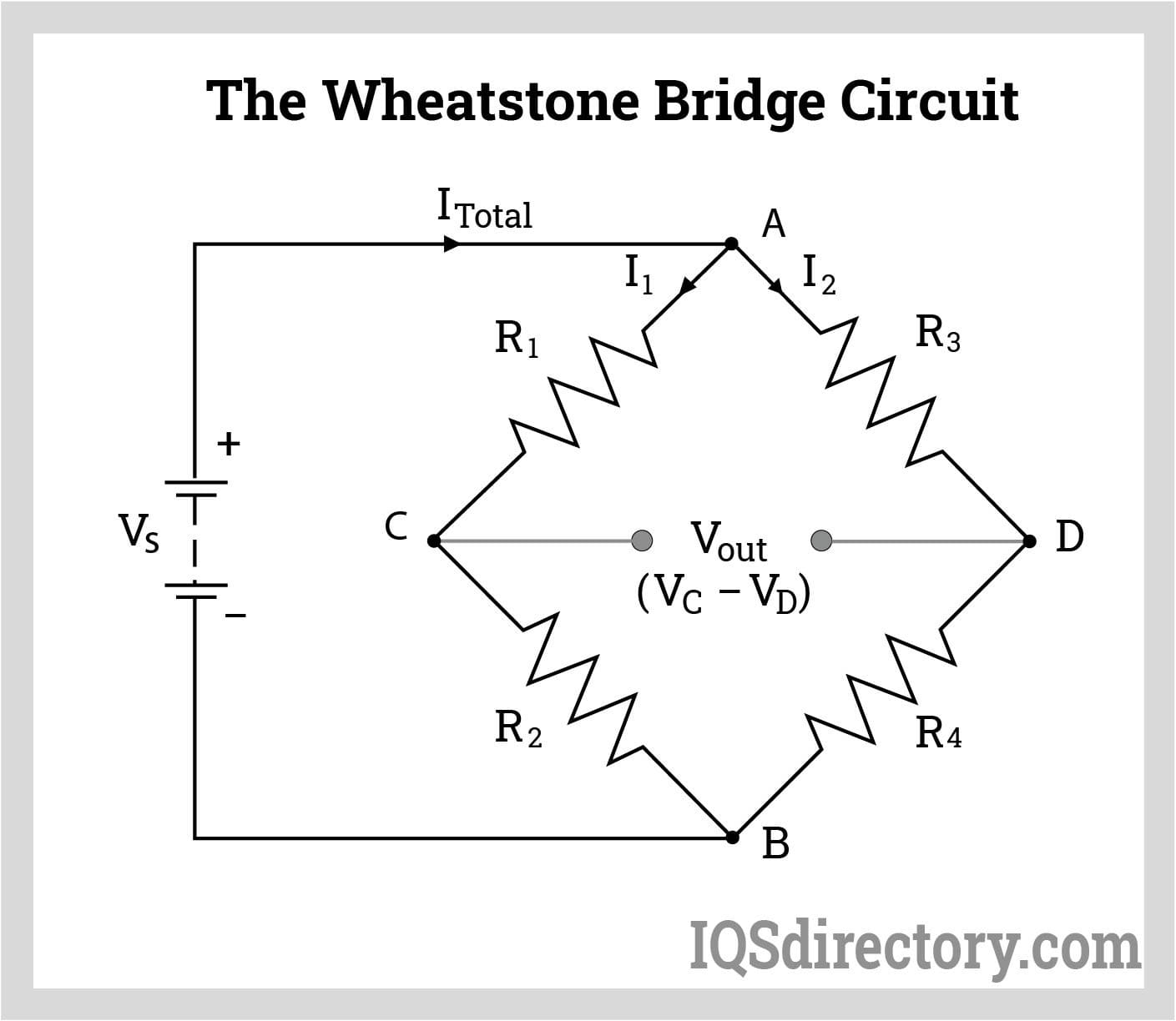
The manufacture of force sensors involves microelectromechanical systems (MEMS) fabrication, which is used to create miniaturized sensors, actuators, and other transducers. MEMS fabrication focuses on developing microsensors that convert mechanical signals into electrical signals.
The process begins with an insulator wafer coated with silicon nitride on both sides of the silicon. Using a photolithographically designed etch mask and a reactive ion etcher, the front side of the silicon nitride is etched to expose the thin silicon, while a nitride ring remains at the outer section.
To protect the semiconducting silicon from the resistors on the oxide, silicon oxide is applied to the front side. On the other side, the nitride is etched to create square windows that resemble thin diaphragms. The silicon is then anisotropically etched in potassium hydroxide (KOH), with the nitride acting as an etch mask and the original oxide serving as an etch stop. After KOH etching, the square silicon diaphragms, which hang over open cavities, are released and sealed with Pyrex® wafers.
Channels are etched into the Pyrex® wafer using hydrofluoric acid and a chromium-gold etch mask. The Pyrex® wafer features a clean reversal face on the back and an engraved face on the front. Once the Silicon on Insulator wafer and Pyrex® wafer are anodically connected, resistors are etched into a metal coating and deposited on the front side through thermal evaporation.
To waterproof and insulate the resistors, a thin film of parylene polymer is applied to the front side. A die saw then separates individual pressure sensing cells or arrays from the bonded wafer pair before testing and packaging. Metal patterning is performed after the metal is placed on the wafer and deposited following KOH etching, but before bonding, as it is not feasible between KOH etching and bonding.
The Wheatstone Bridge Circuit is employed to detect and measure minute changes in resistance, crucial due to the small variations. This setup is utilized in piezoresistive and strain gauge pressure sensors.
Force sensors are generally categorized into four basic types: capacitive, inductive, piezoelectric, and piezoresistive. The key difference among these types lies in the behavior of their sensing elements. Each type is designed with specific structures, endurance, and durability to operate effectively in various environments.
An inductive force sensor uses electromagnetic induction to detect or measure forces, converting the data into voltage or current output through a conversion circuit. When an electric current flows through the inductor, it generates a magnetic field. Inductive sensors can operate effectively in damp or contaminated environments because non-metallic substances, such as liquids or dirt, do not affect the magnetic field. These sensors can measure force by altering characteristics like self-inductance, mutual inductance, or through eddy current creation.
Inductive force sensors are primarily used for low-force measurements and displacement detection. The advancement of bi-directional inductive sensors allows for the measurement of both the amplitude and direction of a force within a plane. Eddy currents in these sensors can reduce inductance by generating an opposing magnetic field.
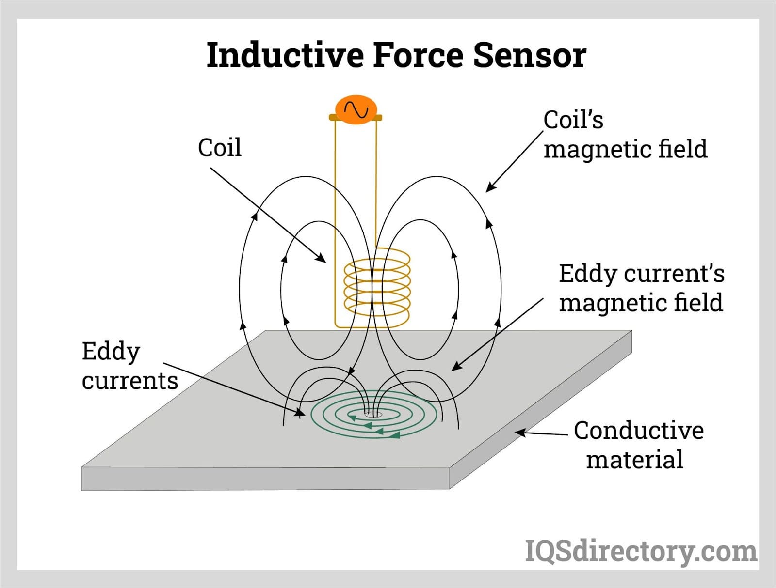
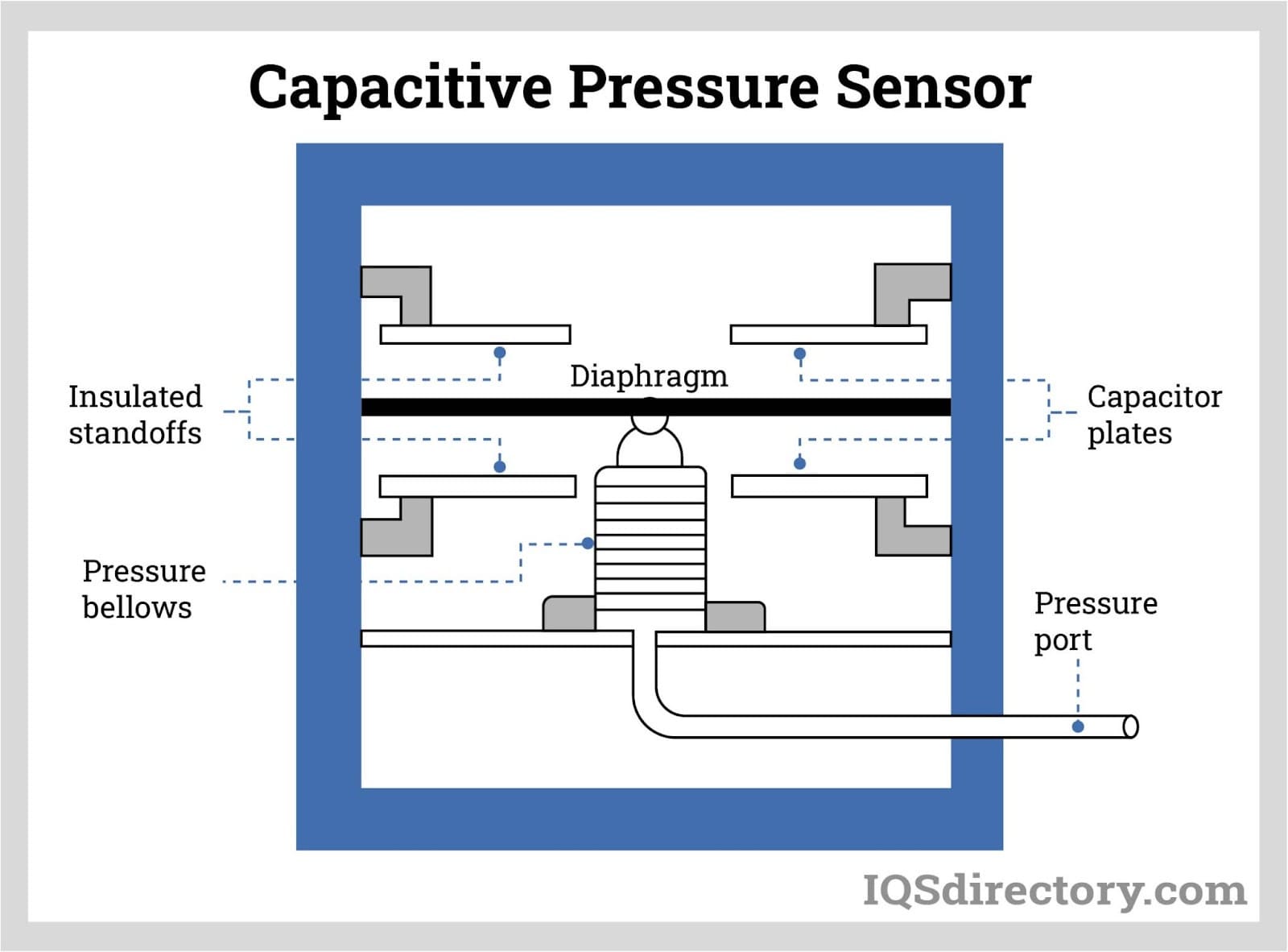
Capacitive force sensors measure and detect objects that are conductive or have a dielectric constant. When force is applied, the distance between the conductive plates within the sensor changes, resulting in a change in capacitance proportional to the applied force. These sensors can be designed with single plates, parallel plates, or interdigitated configurations, each offering specific advantages to meet precise requirements. Capacitive force sensors are valued for their high sensitivity, low power consumption, temperature stability, and cost-effectiveness.
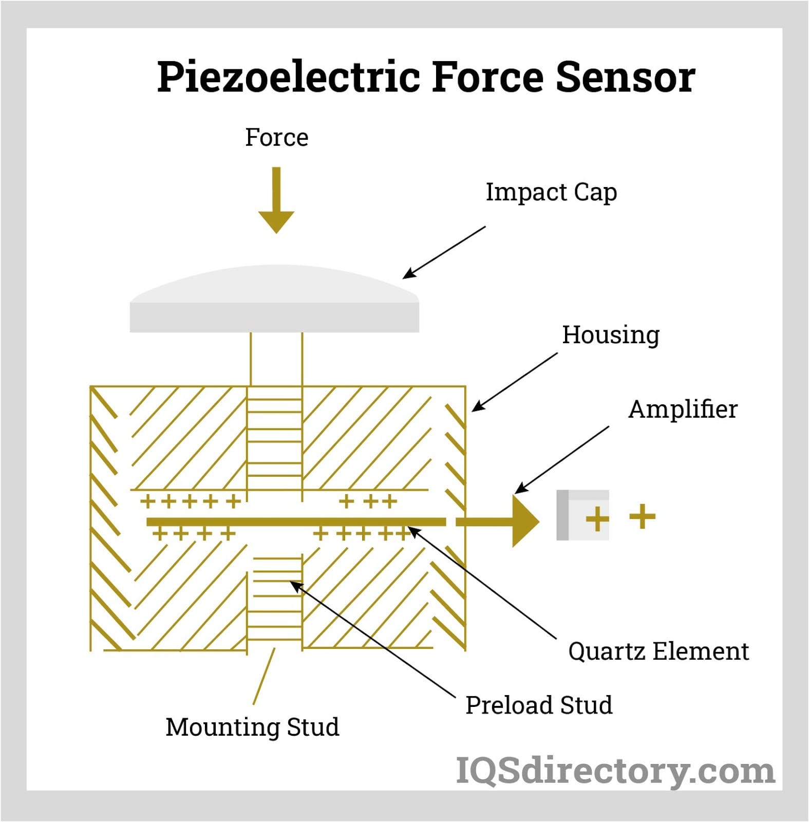
A piezoelectric force sensor utilizes the piezoelectric effect, where a material generates an electric charge in response to mechanical stress. Certain materials produce an electric voltage when forces are applied along specific planes. Piezoelectric force sensors convert changes in pressure, acceleration, temperature, strain, and force into an electrical charge. At the core of a piezoelectric sensor is a quartz crystal that generates an electric charge under mechanical stress. An amplifier then converts this charge into a measurable signal.
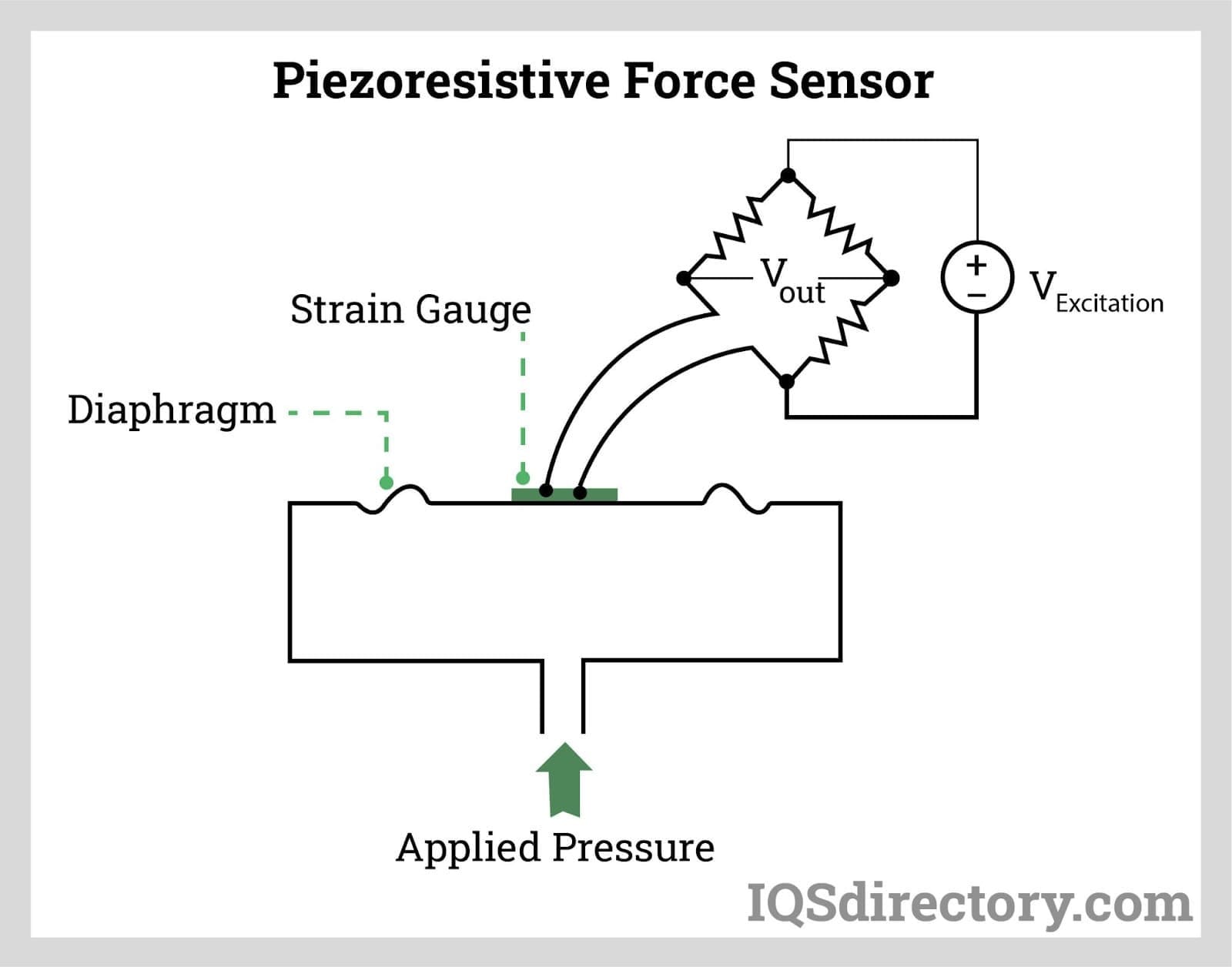
A piezoresistive force sensor operates similarly to a piezoelectric force sensor. It features a thin, flexible diaphragm that deforms under applied force. This type of sensor varies its resistance in response to changes in force, strain, and pressure, providing the necessary output. A strain gauge, which can be either directly manufactured on the sensor or attached to it, serves as the force-sensing material.
The resistive force sensing technique involves the deformation of the resistive element against the substrate when an external force is applied. As the air from the spacer aperture is forced through the air vent in the tail, the conductive material on the substrate contacts the active area. This contact allows for conduction and results in a decrease in the material's resistance.
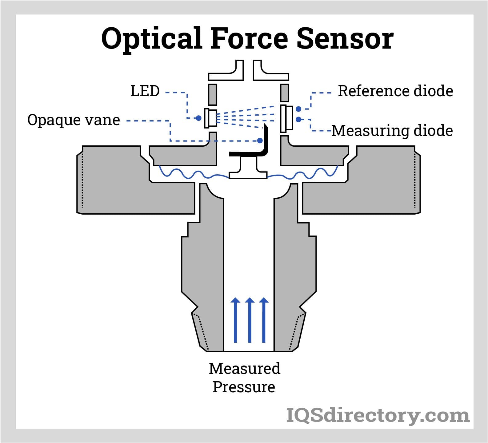
Optical force sensors measure pressure by detecting its effect on light. In their simplest form, these sensors can be mechanical devices that reduce light intensity as pressure increases. They provide highly accurate measurements of small pressure changes through phase differences.
In intensity-based optical pressure sensors, an increase in pressure progressively blocks a light source. The sensor measures variations in the received light as a diaphragm moves, causing an opaque vane to further reduce the LED’s brightness. A photodiode then detects the decrease in light intensity and correlates it with the pressure.
A reference photodiode, which remains unobstructed by the vane, is crucial for a basic optical pressure sensor. It allows the sensor to account for fluctuations in supply voltage and variations in light output due to external factors.
Force transducers are used to measure weight during production and metering force in industrial equipment and systems, such as presses, assembly lines, or end-of-line inspections. Scales are the most common application that come in a wide variety of designs, sizes, and configurations. Force sensors provide accurate results regardless of the materials being weighed. They are built into scales at the self-service checkout at local grocery stores for weighing produce.
In the medical field, force sensors are crucial for applications such as fluid monitoring, MRI machines, dialysis machines, endoscopic surgery, and physical therapy equipment. They play a vital role in ensuring precision and reliability in medical devices, which often require special authorizations and rigorous testing.
For maintaining the health of roads and highways, force sensors are essential. They are used to measure and assess the axle load of commercial trucks, providing precise measurements for effective weight monitoring when loaded. In cars, force sensors measure trailer couplings to analyze driving behavior and provide information about the trailer's weight. They are also employed in vehicle control technology to enhance a driver’s response to various road situations.
In the railway sector, force sensors are used to calculate the weight of cargo, passengers, and tractive forces on the drawbar. This information ensures safe operation within recommended limits. Beyond the trains, force sensors are also utilized throughout the track system.
Aerospace applications rely on force sensors for tasks such as force feedback, flap detection, autopilot operations, and flight recorder data collection. They are used to test and determine the amount of force applied to various objects in flight.
Reference measures are used to produce domestic and worldwide comparability between measured values. Systems are tested by metrological institutes all around the world using incredibly precise force transducers. Reference values are then provided by these institutes for both domestic and global economies. Force transducers are frequently used on test benches to ensure that a desired material load can be properly controlled.
The strain gauge consists of thin wires that can be affected by environmental conditions. Fluctuating temperatures can cause a strain gauge to expand or contract, leading to noise and inaccurate measurements. Corrosion may also degrade the elastic element, reducing the device's lifespan. Additionally, the load cell itself may pose safety hazards in certain environments. For example, in industrial settings such as refineries or chemical plants, there is a risk of igniting flammable liquids and gases. To address these issues, load cells are designed with specific protective measures.
Ingress Protection (IP) Rating: The ingress protection rating measures how well a load cell is protected against solid objects and liquids. The IP rating consists of two numbers: the first indicates protection against solid objects, while the second refers to protection against liquids. An IP rating of IP67 signifies that the device is dust-tight and can be immersed in water. The scale image below shows the definitions of the numbers for solid objects on the left and for liquids on the right. This rating is part of the International Electrotechnical Commission's standard 60529 and provides general guidelines for load cell manufacturers.
| Ingress Protection Rating Scale | |||
|---|---|---|---|
| 1st Numeral | Degree of Protection | 2nd Numeral | Degree of Protection |
| 0 | No Protection At All Against Solid Objects | 0 | No Protection At All Against The Ingress Of Water |
| 1 | Protection Against Solid Objects Greater Than 50mm In Diameter | 1 | Protected Against Fallling Water Drops |
| 2 | Protection Against Solid Objects Greater Than 12.5mm In Diameter | 2 | Protected Against Fallling Water Drops At An Angle Of Up To 15° |
| 3 | Protection Against Solid Objects Greater Than 2.5mm In Diameter | 3 | Protected Against Sprayed Water Drops At An Angle Of Up To 60° |
| 4 | Protection Against Solid Objects Greater Than 1.0mm In Diameter | 4 | Protected Against The Splashing of Water From Any Direction |
| 5 | Protected Against The Ingress Of Dust In Such An Amount That It Will Not Interfere With The Operation Of The Equipment | 5 | Protected Against Water Jets From Any Direction |
| 6 | Total Protection Against The Ingress Of Any Dust | 6 | Protected Against Powerful Water Jets From Any Direction |
| 7 | Protected Against The Ingress Of Water When Temorary Immersed Of Between 0.15 m And 1 m | ||
| 8 | Prtected Against The Ingrss Of Water When Continuously Immersed To A Specified Depth | ||
Hermetically sealed load cells provide the highest level of protection. This is achieved through welding, epoxy sealing, or glass-to-metal bonding, and the internal cavity is filled with pressurized inert gas. These load cells are both air and water-tight, as indicated by their Ingress Protection (IP) rating.
These load cells are designed for use in normal indoor environments or protected outdoor applications. They are typically covered with soft resin or rubber for environmental protection. However, this type of protection makes the strain gauge susceptible to moisture and temperature fluctuations.
Explosion-proof load cells are designed to contain or prevent explosions that may originate within the device. For equipment with internal cavities exposed to flammable gases, these gases can infiltrate the cavity, creating an explosive mixture. Sparks or heat from the load cell could ignite this mixture, leading to an explosion. An explosion-proof rating is achieved through a combination of containment, energy limitation, and segregation measures.
When designing a system that incorporates load cells, it is important to consider the following factors:
Rated Capacity or rated load is the maximum capacity or weight that a load cell can measure. When designing a system to measure a certain weight, the load cell rated capacity must be greater than the weight.
Overload Rating (Safe) is the maximum load that can be applied to a load cell without causing a permanent change in measuring characteristics or performance.
Overload Rating (Ultimate), on the other hand, is the maximum load which can be applied without causing damage to the load cell.
Rated Output is the electric output signal per strength of the excitation voltage expressed in mV/V.
Zero Balance is the electric output signal with rated excitation voltage when no load is applied.
Excitation Voltage is the voltage supplied to the transducer circuit.
Non-linearity is the load cell‘s calibration curve deviation from a straight line, starting from zero load up to the cell‘s maximum rated capacity. This is the weighing error over its entire operating range.
Hysteresis is the difference between two load cell output readings for the same applied load. One reading is obtained by increasing the load from zero, while the other by decreasing the load from the load cell‘s maximum rated capacity.
Combined Error is the combination of non-linearity and hysteresis.
Repeatability is the maximum difference between load cell output readings for repeated loads under identical loading conditions.
Temperature Effect on Rated Output is the deviation in output readings caused by temperature changes.
Temperature Effect on Zero is the deviation of the zero balance caused by temperature changes.
Input and Output Resistance is the resistance of the load cell‘s circuit measured at the positive to negative and negative to positive excitation leads, respectively.
Insulation Resistance is the resistance of the load cell measured between the load cell circuit and the load cell housing.
All industries that require weighing use load cells due to their compact profile as compared to mechanical scales. The load cell application is not limited to weighing; load cells are also used in automation and structure monitoring. Listed below are the general applications of load cells.
In industrial and manufacturing plants, load cells are utilized to measure the quantities of raw materials and finished products. They are essential for monitoring material levels along the process line, allowing for adjustments to process parameters as needed. Load cells are commonly employed in industrial equipment, including hoppers, silos, tanks, conveyors, and packaging machines.
Among the popular equipment utilizing load cells are universal testing machines and laboratory scales, which require very high precision. However, other force transducer principles beyond the strain gauge are also employed in various applications.

Output signals from load cells can serve as feedback for process line automation. They are commonly used in automatic packaging, distribution, and sorting systems to enhance efficiency and accuracy.
Load cells are widely used in truck platforms, weighbridges, cranes, and railways. In these applications, they primarily measure the weight of goods loaded onto trucks and containers.

To ensure optimal performance of a load cell, it is crucial to follow the manufacturer's installation guidelines. Manufacturers are available to provide guidance and insights on how to effectively use their load cells in a project.
Proper framing and fixtures are critical for load cell installation. They help maximize stiffness while minimizing weight and costs. The frame must support the measuring device and be rigid enough to resist deformation and flexing.
Factors such as compressors, pumps, actuators, and engines can cause vibrations that affect the frame. Additionally, seismic activity in certain areas may interfere with measurements. Placing the frame on a hard, flat surface can significantly reduce the impact of these vibrations.
The frame should be designed with allowances for thermal expansion and contraction to prevent damage to both the load cell and the frame itself.
The load cell frame should be designed to minimize rotation and movement, which helps prevent damage to the frame's hardware.
When assembling the frame, it should be done away from the load cell to avoid potential damage from stray currents produced during welding.
All loads and forces must be directed through the load cell to ensure accurate measurements. If not properly aligned, the measuring system will not provide correct readings. The axial direction, marked on the load cell, is perpendicular to the loading surface.

Force sensors are transducers that transform mechanical input forces like weight, tension, compression, torque, strain, stress, or pressure into an electrical output signal whose value can be used to...

A load pin is a sensor utilized to measure force or weight in various research, control, measurement and testing applications. The load pin force sensor converts a force into an electrical signal. The load pins provide...
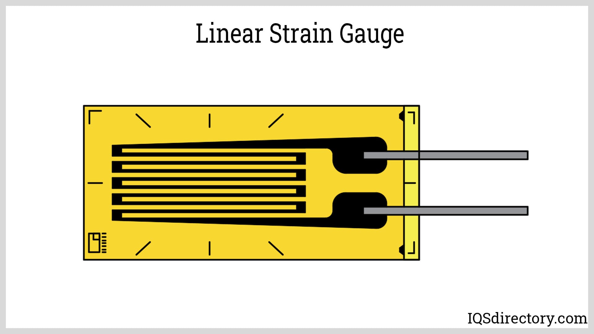
A strain gauge, or strain gage, is a sensing device used for measuring strain experienced by an object. It is made from a long, thin piece of conductor bonded to an elastic backing material called a carrier...
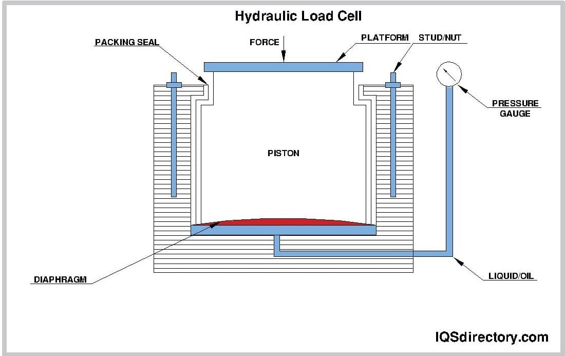
At the heart of every weighing device is a sensor called a load cell. When an item is put on a load cell, it senses the force of the gravitational pull of the weight, which an electronic circuit processes to display...
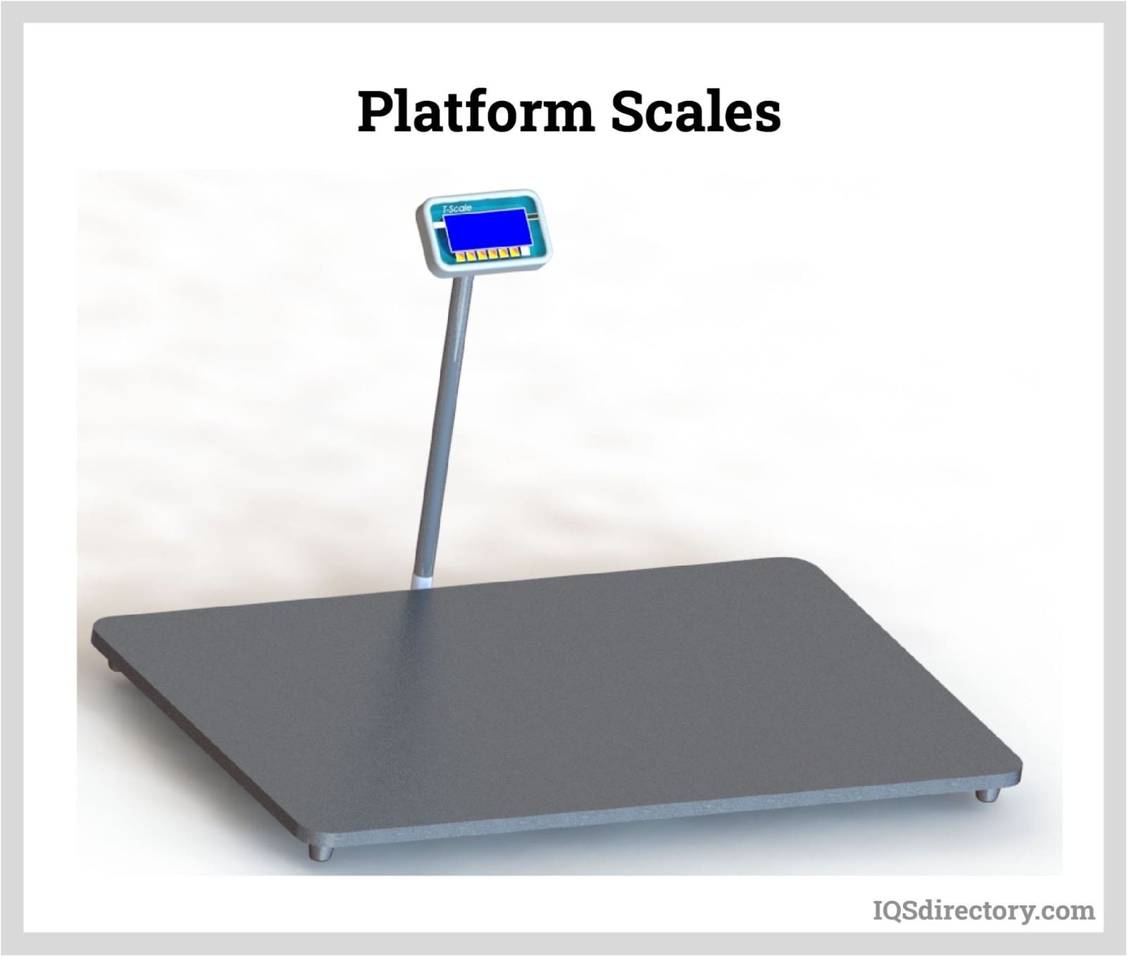
A platform scale is a scale that measures the weight of objects loaded on a flat platform. The function of the platform is to transmit the weight of the object to the internal measuring device and to support the object during weighing...