Force Sensors
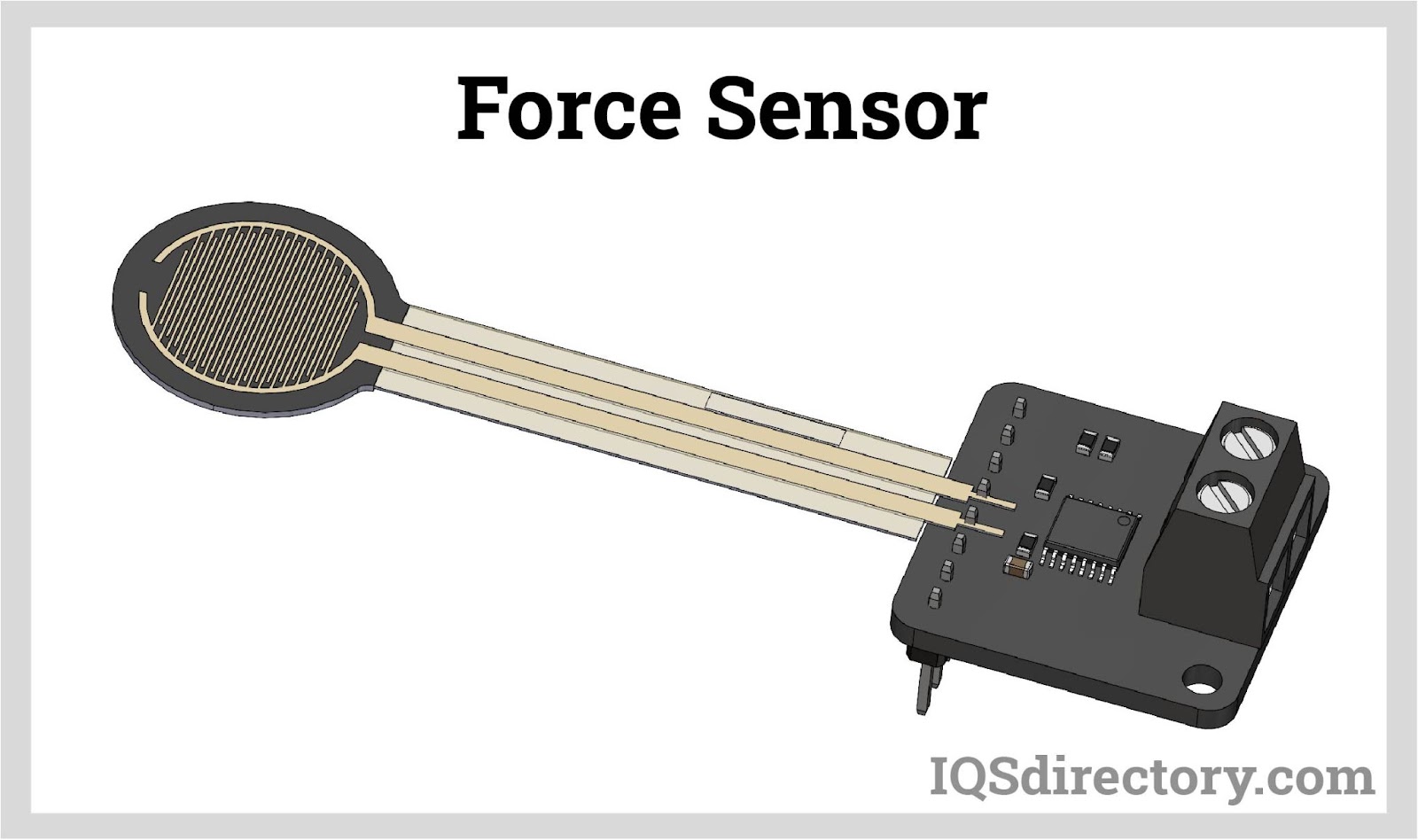
Force sensors are transducers that transform mechanical input forces like weight, tension, compression, torque, strain, stress, or pressure into an electrical output signal whose value can be used to...
Please fill out the following form to submit a Request for Quote to any of the following companies listed on Load Pins .
Descriptions of types of load pins and their use and a list of loan pin manufacturers
Topics covered in this article are:
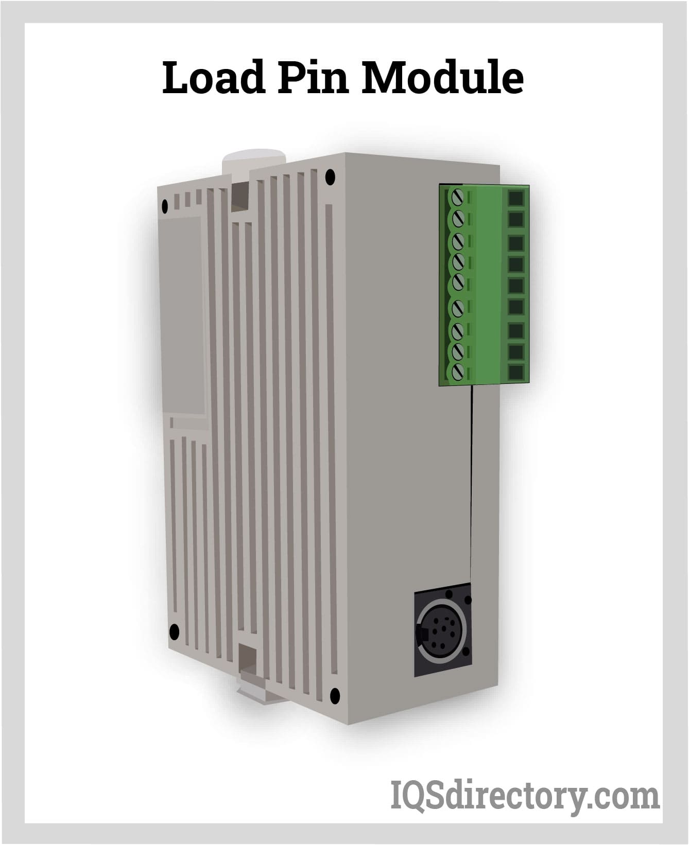
A load pin is a type of sensor designed to detect force or weight in numerous settings, such as research, control, measurement, and testing applications. They are specialized force sensors that transform applied force into an electrical signal. Load pins deliver reliable and precise measurements even under harsh conditions, including locations like outer space, seas, mines, and deserts. These sensors are highly valued for identifying applied forces and playing a crucial role in measuring and preventing excessive loads transmitted via pin joints.
One notable advantage of force sensors, particularly load pins, is the integration of internal strain gauges, a technology that has been employed for over six decades, broadening the application of load pins. This advancement is feasible because the pins feature a partial internal bore along the neutral axis to accommodate and shield internal instrumentation, effectively protecting the gauges from environmental factors. Load pins are crafted from high-strength stainless steel or alloy steels, ensuring optimal linearity and repeatability.
Standard load pins are universally adaptable, but the demand for custom load pins has grown when addressing unique needs. These can be tailored to exact application requirements and specifications. The custom design process is both cost-efficient and can be accelerated to fulfill urgent demands.
Load pins, also referred to as "Clevis pins" or "dynamometric axles," have a shaft-like structure incorporating a Wheatstone bridge for detecting double shear forces or loads from overhead equipment. Load cells, known as load pins, are utilized as pivot, clevis, sheave, and equalizer pins or other load-bearing components.
Diverse types of load pins are employed in cranes, winches, elevators, hoisting mechanisms, sheaves, shackles, bearing blocks, and pivot points. These pins function as force-measuring strain gauges. Similar to load cells, load pins track alterations in the electrical signal induced by force, which is then converted into weight measurements.
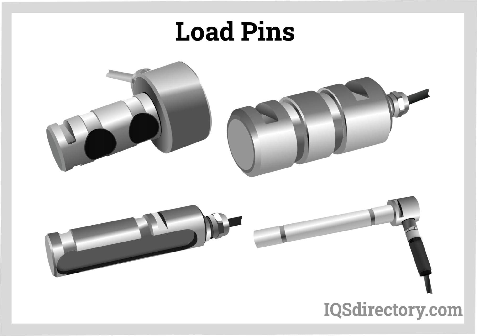
Load pin strain gauges are interwired into a Wheatstone bridge circuit. When excited by a fixed voltage source, the bridge circuit produces a variable output voltage that is proportional to the force applied to the elastic element. The mechanical input is converted into an electrical output reading by successive conversions:
A load applied to a load pin produces a deformation, which is measured by its strain gauge and converted into a measurable electrical signal in the Wheatstone bridge.
The area of a load pin between the measured forces is defined by two grooves. The fixed applied pressure is the opposite of that produced by a lug or sheave. The load pin measures the force or pressure and transmits a reading to a weight display.
Standard pins can be replaced with load pins without reducing headroom or jeopardizing a device's functionality or safety. Load pins continuously monitor loads, promotie safety, and prevent costly overload damage.
Industries with overhead machinery require the use of load pins in order to provide safe working conditions. Load pins are made of corrosion-resistant stainless steel with internally placed strain gauges, which makes it possible to use load pins in any type of environment.

A load pin is a strain gauge that uses a Wheatstone bridge circuit that generates a variable output voltage proportional to the force acting on an elastic element that is activated by a fixed voltage source. The mechanical input quantity is changed to an electrical output quantity by successively changing multiple physical quantities.
Using fundamental equations of strength from material science, force is transformed into mechanical stress. Following Hooke's law, the calculated stress is turned into strain, with the strain indicator being a relative resistance variation. The Wheatstone bridge translates the change in resistance into a change in output voltage.
Load pins replace clevis, sheave, pivot, normal shaft, and equalizer pins. When a load or force is applied, a load pin deforms. The strain gauge in a load pin records the deformation and transforms it into a quantifiable electrical signal in the Wheatstone bridge.
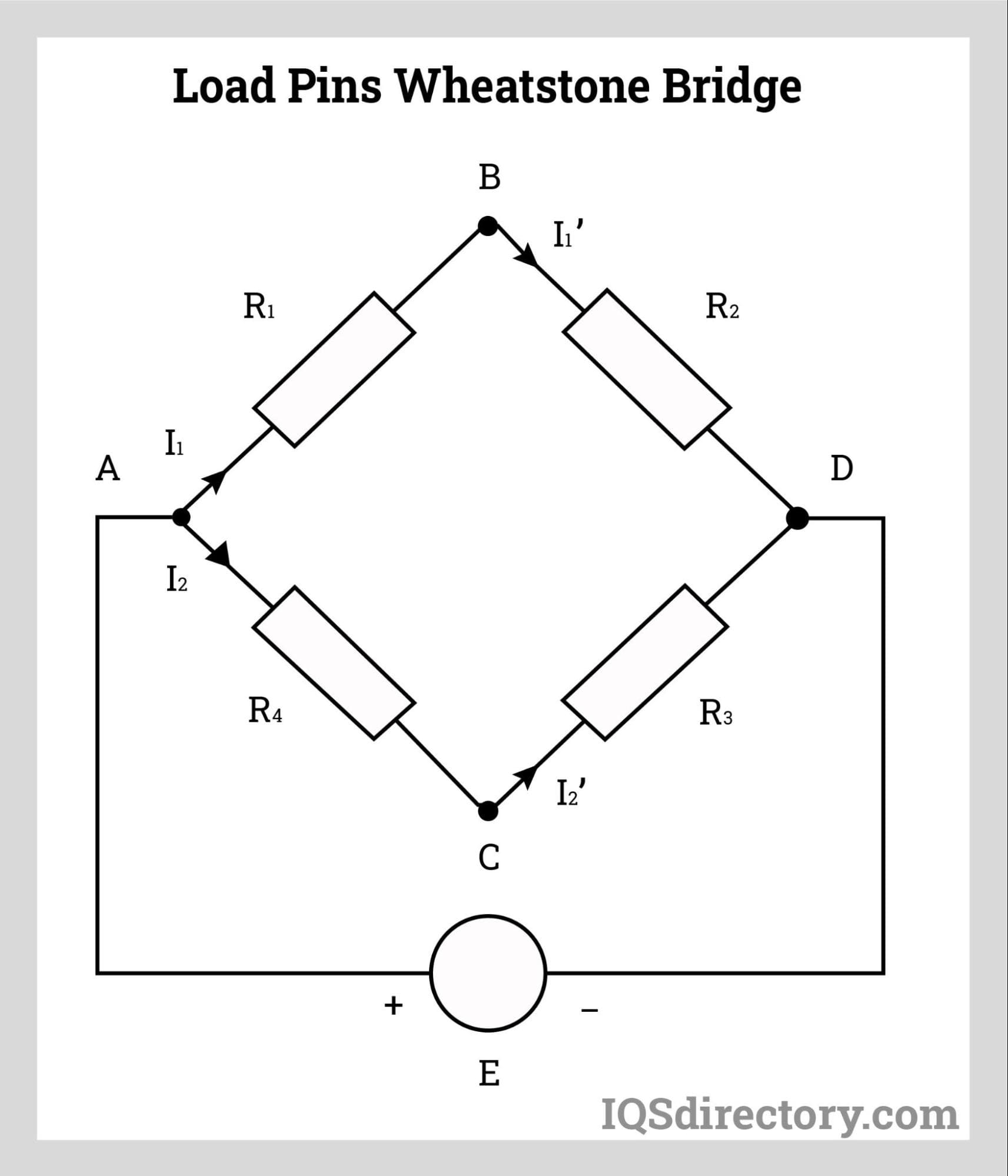
The key consideration in regard to the performance of a load pin is any change in the geometry of the pin and the loading structure or loading conditions. Minimal bending of a structure can change the bearing areas or bending of a load pin and will affect its performance. Load pins are designed to fit into an existing structure. They are constrained by the size and load of a structure.
The amount of force that will be evaluated and the size of an increment are necessary. To weigh safely and accurately without running the risk of overloading or operating too close to capacity, load pins must be rated for the load of a structure. Their capacity should match the requirements of an application. Since they rely on electrical impulses, the millivolt output of each increment drops as the resolution increases. As the millivolt output decreases, it may become harder to detect minor changes.
The initial steps in the purchase of load pins is in regard to a manufacturer’s compliance with NTEP and NIST standards, especially in cases where a load pin is being used in a hazardous environment. Expert advice and guidance from manufacturers is critical to the selection process and assists users in purchasing the correct load cell for their application.
Any materials that may come in contact with a load pin must be considered, such as corrosive gases, liquids, or solids. A load pins IP or ingress protection rating assists in determining a load pins ability to endure a particular environment. Guidance from producers, as well as their expertise, helps in this aspect of the selection process.
The temperature of a location will impact the performance of a load pin. If the user intends to use the load pins in extremely hot or cold conditions, it is necessary to select a load pin that can function properly in such conditions. In addition, if high resolution is necessary, factors like vibrations, airflow, and wind need to be considered. Some load pins are capable of counteracting these factors. Their selection will depend on the requirements of the application and its environment.
Load pin manufacturers will assist users in selecting load pins that have been certified by the National Type Evaluation Program (NTEP) for the capacity and resolution for a user's application. In addition, the National Institute of Standards and Technology (NIST), in its handbook 44, has additional standards for load pins and their use, which manufacturers and producers use to assist in load pin purchases.
A load pin is a sensor used in various research, control, measuring, and testing applications to quantify force or weight. The load pin force sensor transforms a force into an electrical signal. The load pins offer reliable and accurate measurements even in harsh environments like space, the ocean, mines, and deserts. Identifying applied forces, measuring overloads, and preventing them from being transferred via the pin joints are some examples of the utility of load pins due to their design.
The internal strain gauge's inclusion into force sensors, and load pins, is one of their key benefits. The internal gauge technology enables a wider application of load pins. This wider application is made feasible because the pin is not entirely solid; instead, a small internal bore is machined along the neutral axis to house and safeguard the internal instrumentation, separating the gauges from the outside world. In addition, the load pins are made from high-strength stainless or alloy steel materials to maximize linearity and repeatability.
Numerous applications are suitable for standard load pins, and as the number of applications for load pins has substantially increased, custom pins have also grown in demand and necessity. Therefore, a significant benefit is the option to acquire a custom load pin made to fit their requirements.
When a force acting on a structure needs to be quantified, the necessary equipment is often expensive and difficult to install. Load pins are a key element which solves that problem as they are installed as another direct component of an assembly to replace non-instrumented pins or shafts already existing in the load path. When a force is applied to the instrumented load pin, the strain gauges produce an output signal that allows load measurement, including high stress and overload conditions.
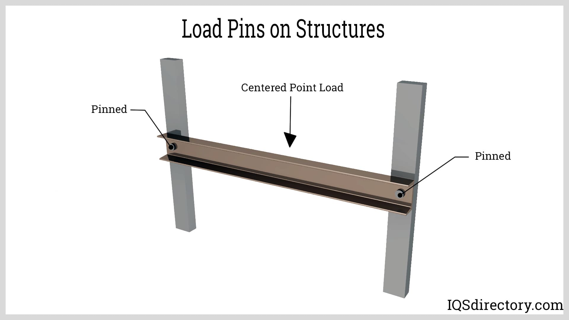
Various force measurement applications across various industries use load cells, load pins, tension links, bolts/studs, and other force sensors and systems. Simple force-measuring systems to cutting-edge products like NASA's Mars rovers, the Space Shuttle launch pad, and hydrostatic or submersible vehicles utilized deep below the ocean's surface are all examples of uses. Generally speaking, there are two types of applications for load cells:
Using load cells for product, component, and system research, development, and testing falls under this first category. For example, load sensors are frequently used for testing and requirement verification for new hardware designs, force distribution analysis, operational force determination, and overload or structural capabilities. In addition, computer modeling and simulation tools are increasingly used as design tools for new hardware development. As a result, the load cells are frequently used to collect real-world load and force data.
Load sensing is also used to test established, mature hardware designs when use is expanded to encompass new requirements or some form of enhanced scope or capacity and additional testing is necessary. Load cells are not just used to test/evaluate new hardware designs.
The second utilization area is centered on product or process control applications rather than new or used hardware design or testing. In these situations, the load cell products regulate a certain force or operation to guarantee that the desired force is achieved, either directly monitored or incorporated into a full-fledged automated system. The load cell systems can alert or set off various programmed actions or events. As an alternative, other control applications include monitoring forces during an operation to guarantee that specific overload or unsafe circumstances, if encountered, are identified promptly.
Several applications and illustrations of how load cells are used in control applications to make sure process force is attained, or conversely, that it is not over-ranged or exceeded are provided in this area.
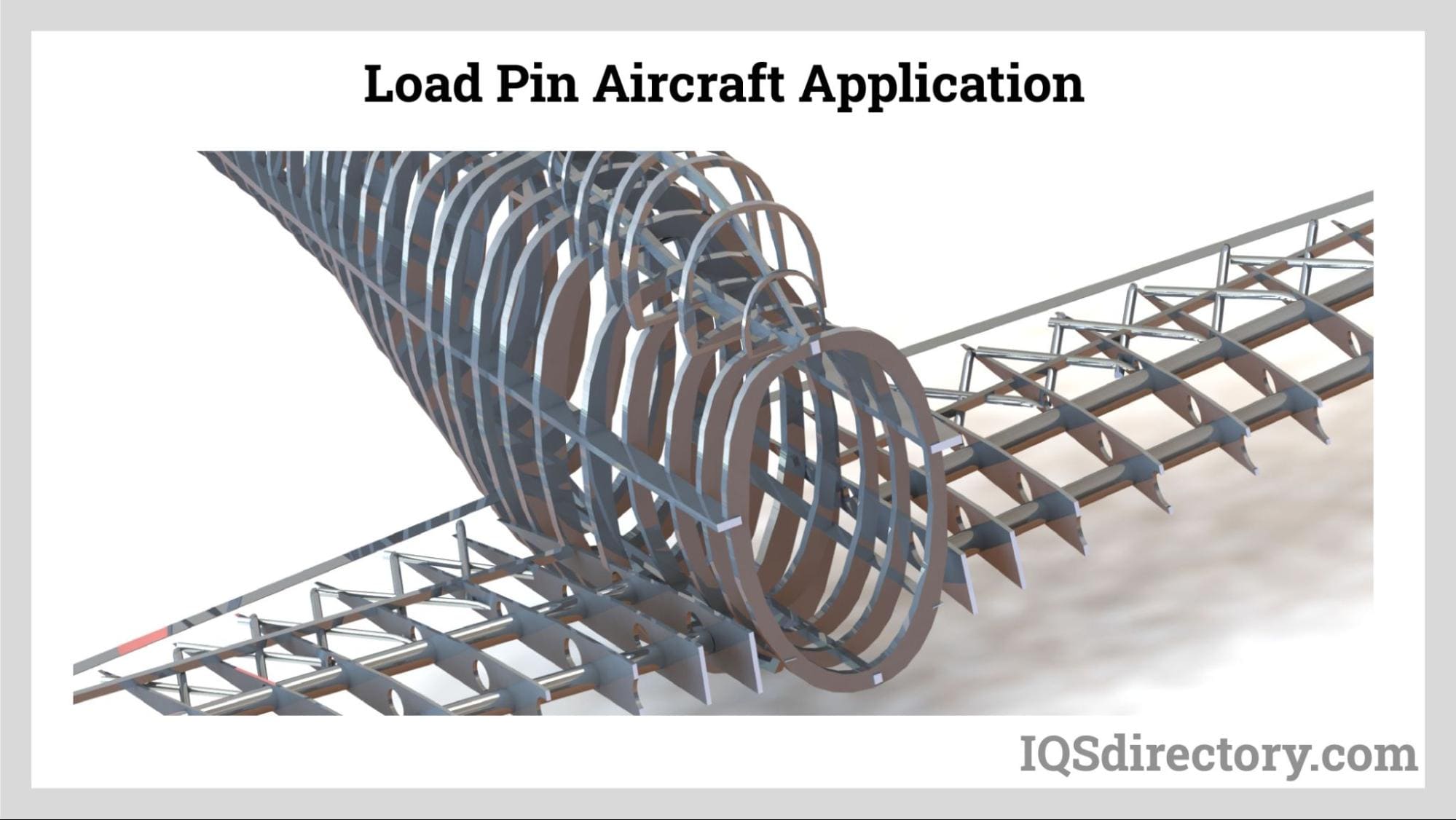
There are several applications for load pins; a selection is given below.
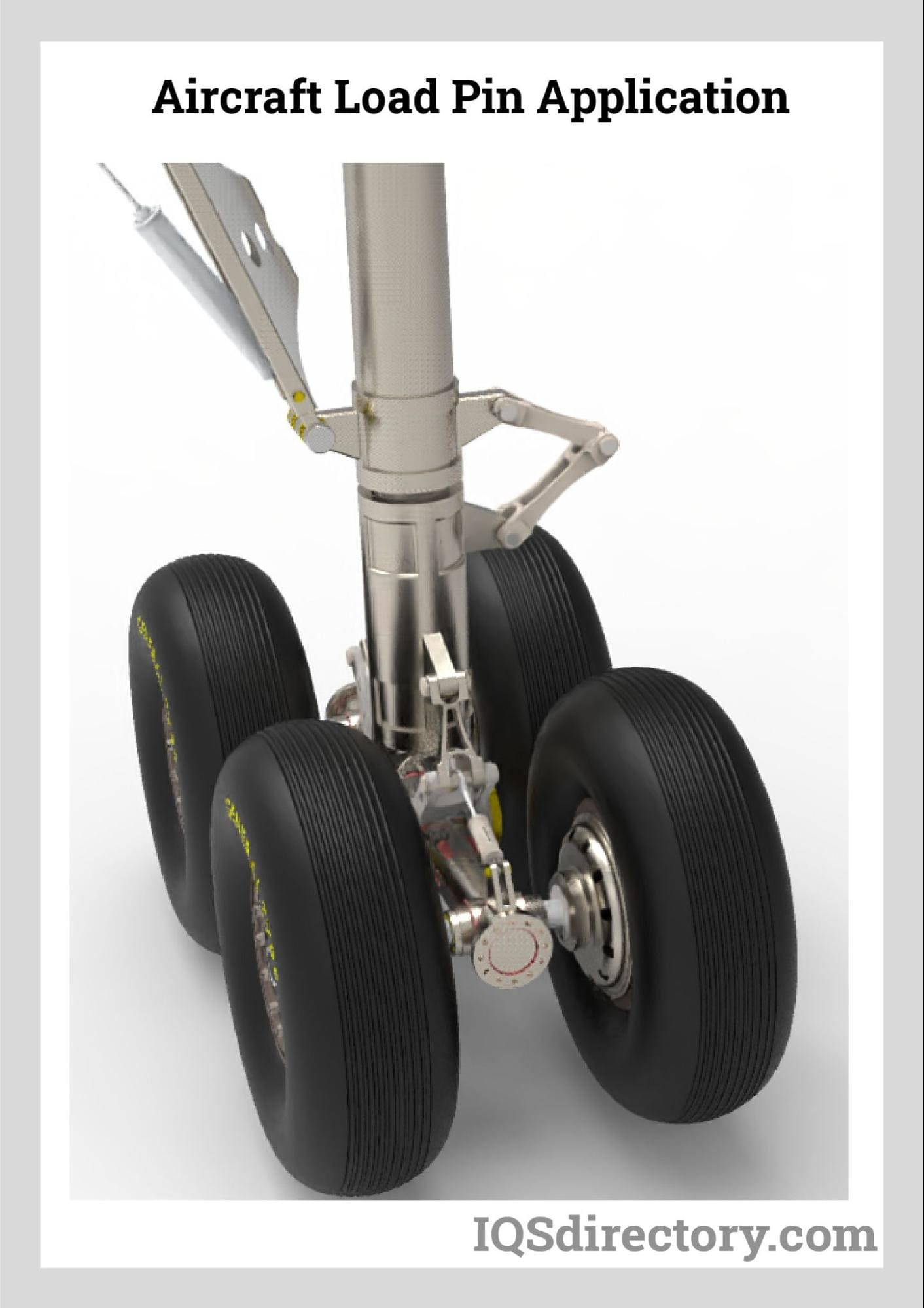
Many industries, including aerospace, marine, oil and gas exploration, the military, aviation, and the automobile, depend on load pins. It is necessary to show that force measurements are correct to avoid product liability and safety concerns. Compliance with ISO and AS certifications frequently focuses on traceability to NIST standards.
Calibration at regular intervals is required to ensure the load pin is operating within specifications, as all load pins are susceptible to degradation through usage, abuse, drift, or aging. Electrical impact, mechanical effects, instrumentation errors, loose wires, etc., can reduce load pin performance and reliability over time. As particulate matter can accumulate around load pins even in clean surroundings, failure to inspect or clean load pins is another important aspect that might result in operational problems. Performing annual calibrations helps to guarantee optimal performance.
Since all load pins are subject to deterioration due to use, mistreatment, drift, or aging, calibration at regular intervals is necessary to ensure the load pin is performing within its specification. Over time, wear and tear can degrade performance and make a load pin less reliable due to electrical influences, mechanical effects, instrumentation faults and loose cables. Failure to inspect or clean load pins is another significant factor that can lead to operational issues, as particulate matter can build up around load pins even in clean environments. Regular, yearly calibrations ensure optimal performance.
Load pins are manufactured from robust stainless-steel or other high strength alloy steels. They have a high corrosion resistance and can be designed for use in harsh environments. Load pin systems include thermal compensation, are easy to install and maintain, and are an economical solution to difficult load measurement conditions. An optional wireless transmitter has integrated electronics that enables monitoring without cables. Properly installed and calibrated load pins can be drop-in replacements, minimizing installation costs, mitigating the requirement to add additional hardware components to the load path.
Twin bridge, two independent strain gauge circuits, is offered by clevis pins. Dual bridge transducers can utilize just one bridge for measurement while saving the other bridge as a backup, or they can use both bridges simultaneously for control and measurement.
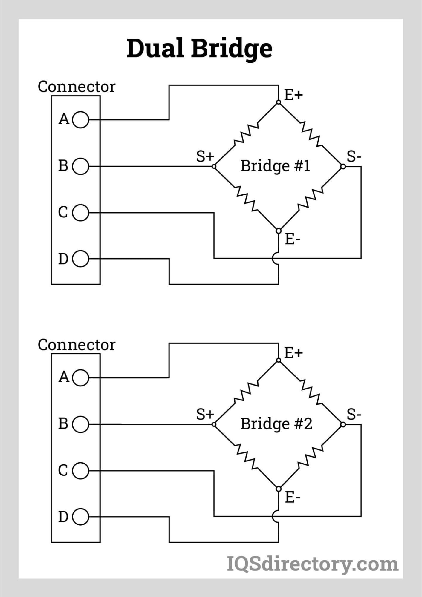
With either single or dual connectors, electrical terminations can be either radial or axial (dual shown below). Cables that are permanently attached are also an option.
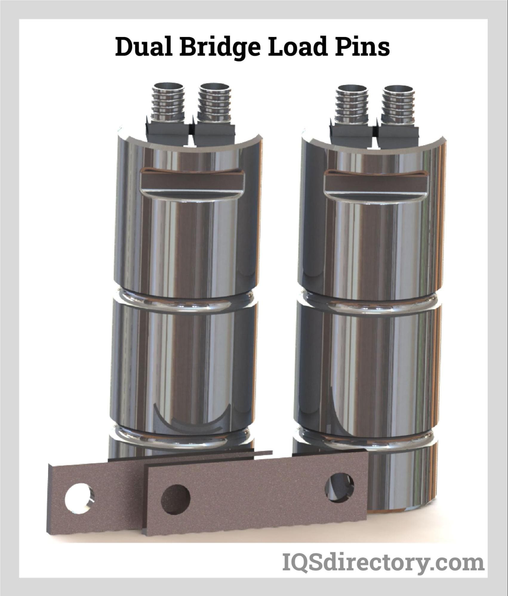
In situations where cable installation may be challenging, expensive, or unwelcome, the wireless load pin offers a high-performance wireless telemetry solution. The system offers great measurement precision, resolution, and stability combined with long battery life. In addition, software tools enable rapid and simple device configuration, calibration, data logging, and recording interfaces.

Force sensitivity load pins, sometimes called clevis pins or clevis bolts, are special load sensors that utilize the internal strain gauge transducer technology created and used in flat load cells and tension links. By replacing the existing shear pins, clevis bolts, load pins, shear axles, and many other types of pinned joints for the aerospace, automotive, marine, and military industries, these load pins, and clevis bolts provide exact force measurement.
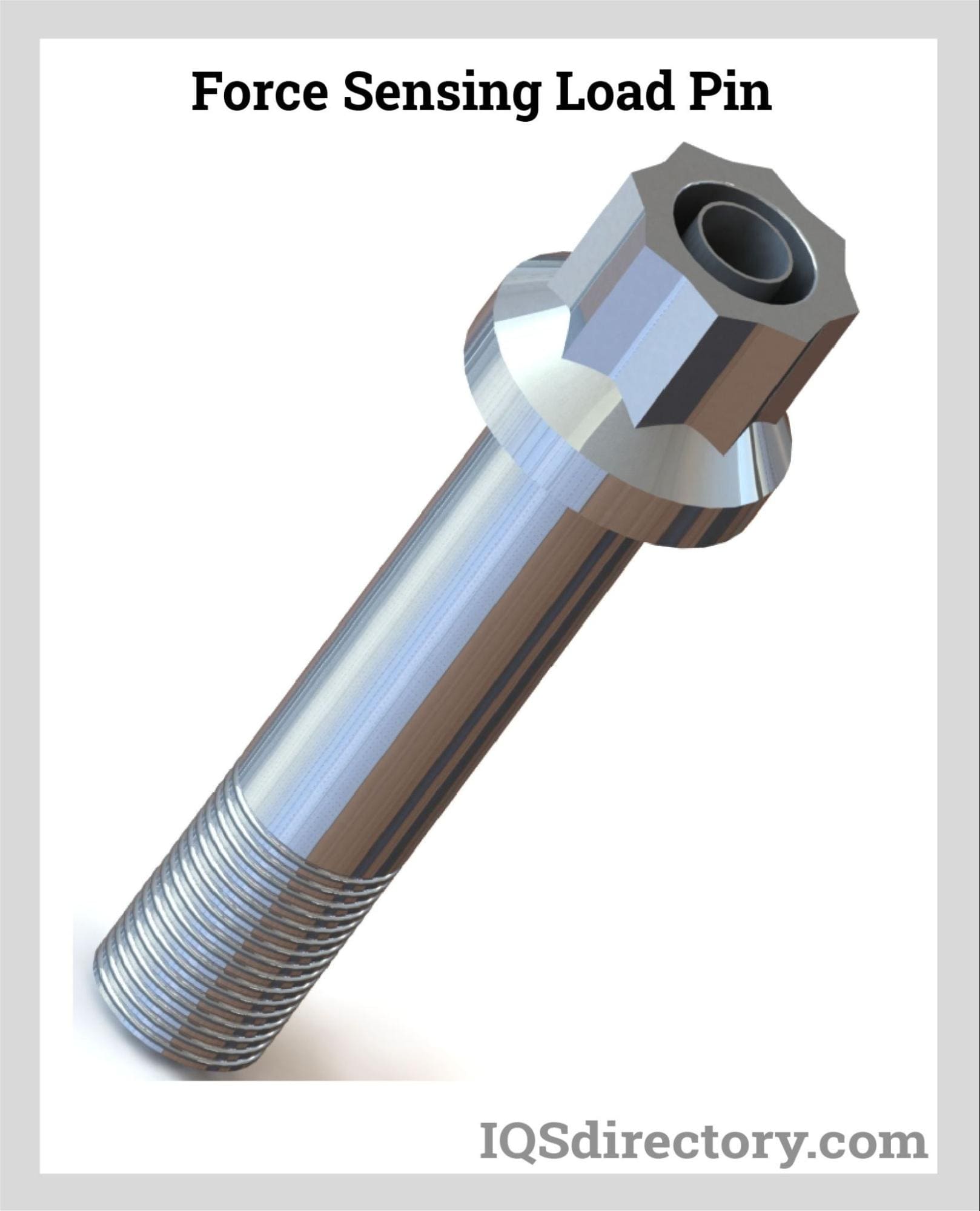
The strain gauges are installed at two sites at the clevis to clevis eye interfaces and are sealed inside tiny axial holes within the load pin. The strain gauges are carefully positioned and orientated at a neutral plane concerning one particular direction of pin loading to detect just those strains caused by the shear stresses at these two sections.
The four strain gauges—two at each location—are electrically connected to create a full bridge. Since each strain gauge's signal is additive, the output of the bridge is proportional to the total loads communicated by the pin's shear planes. The circuit often includes temperature compensation, signal trim (if applicable), and balancing resistors that terminate in suitable connector sockets or integral cables.
Detailed calibration data up to 500,000 lbs. are included in standard force sensing load pins/bolts. Therefore, standard force sensing load pins/bolts need higher capacity calibration data. Although calibrations are meant to mimic installed settings, it is advised that an in-place calibration be carried out to take into account any installation, tolerance, and alignment impacts that may alter sensor data.
These standard clevis pins are often utilized in new applications where the designer can construct the exact load pin joint around the standard clevis pin specifications to maximize the performance of force measurement. Additionally, the conventional clevis pin may suit existing load pin joints or can be added by using bushings or changing the clevis assembly.
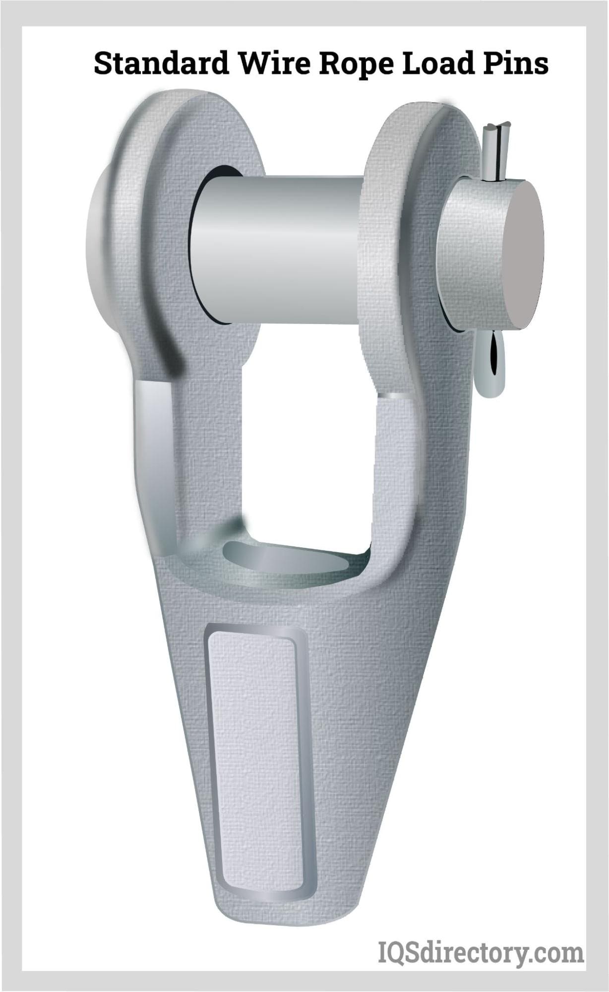
Force sensitivity load pins, sometimes referred to as clevis pins or clevis bolts, are load sensors that use internal strain gauge transducers and are used in flat load cells and tension links. By swapping out the current clevis pins in typical wire rope socket gear, these load pins and clevis bolts provide precise force measurement and monitoring.
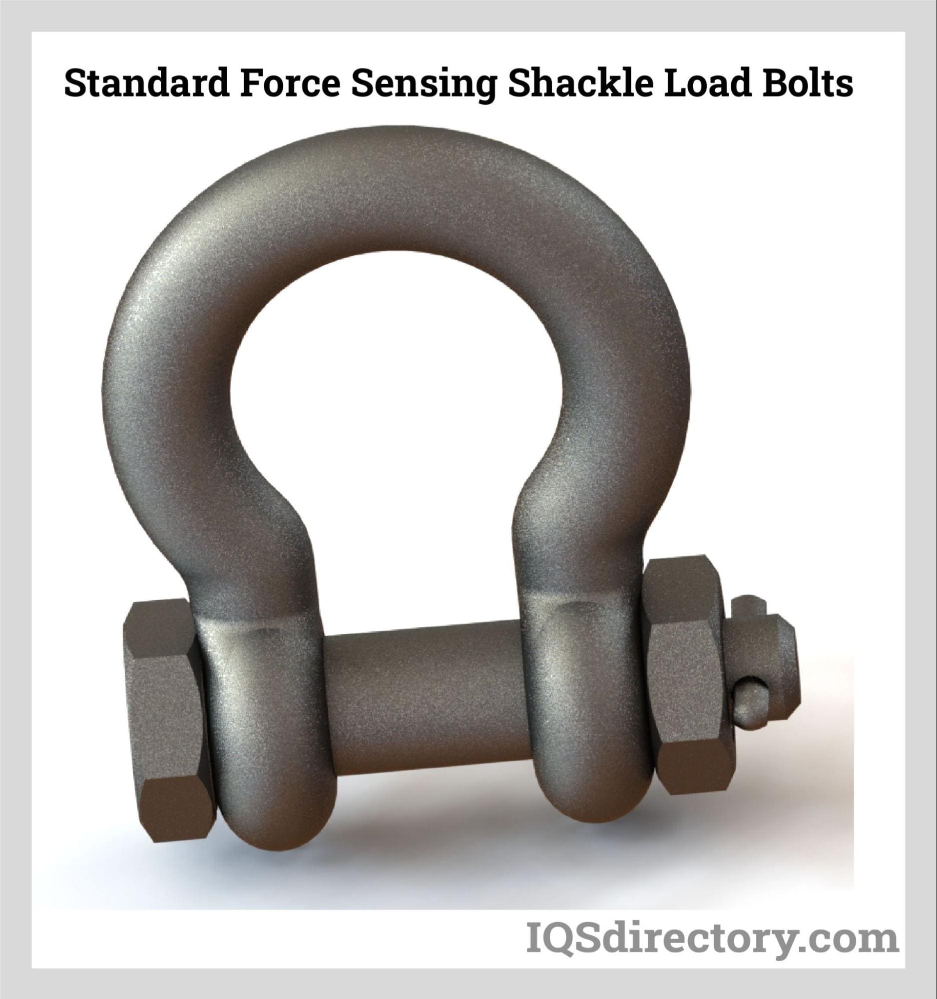
The force sensing shackle bolts use the internal strain gauge transducer technique, also used in their flat load cells and tension links. By swapping out the current pins or bolts in typical Crosby anchor and chain shackles, these shackle bolts provide precise force measuring and monitoring.
Detailed calibration data up to 500,000 lbs. are included with standard force sensing shackle load bolts. Therefore, standard force sensing shackle load bolts need higher capacity calibration data. Although calibrations are meant to mimic installed settings, it is advised that an in-place calibration be carried out to take into account any installation, tolerance, and alignment impacts that may alter sensor data.
Clevis pins or bolts are incredibly resilient even under the worst weather and working conditions. As a result, these goods are widely applicable and have a long useful life. And are being utilized on numerous installations that call for force measuring in a shackle application.
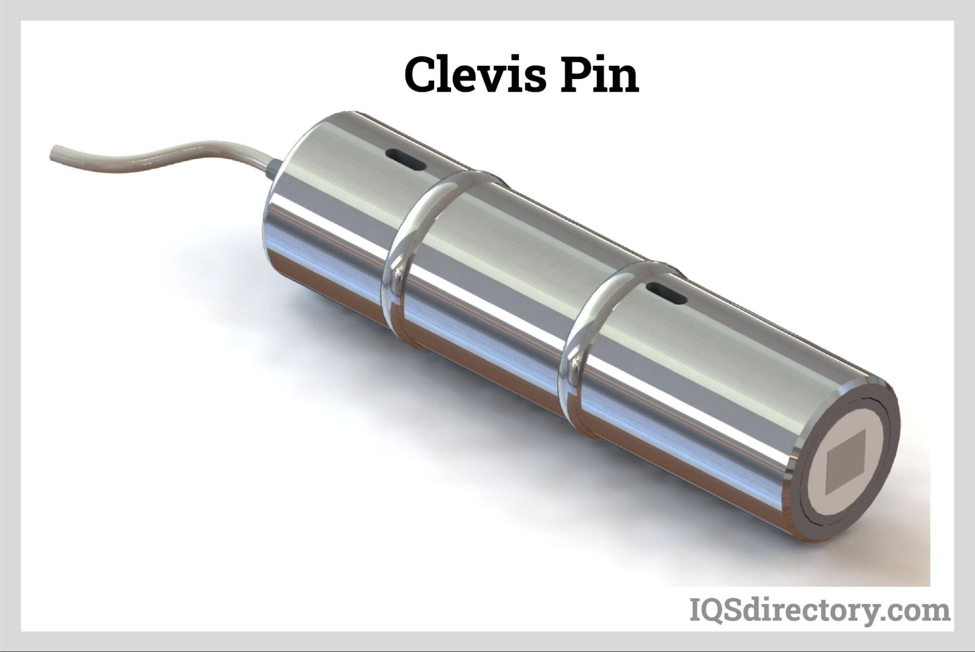
Sheave and pulley systems use a variety of instrumented load pin designs. The user can create a sheave around our basic CPA clevis pin or have a bespoke pin made for an existing sheave design with a specific measurement capacity and geometry, enabling easy installation and maximizing measurement capacity. Observing the pin's reaction load, the instrumented sheave pins are frequently used to gauge line tension. The following formulae can be used to calculate the line tension.
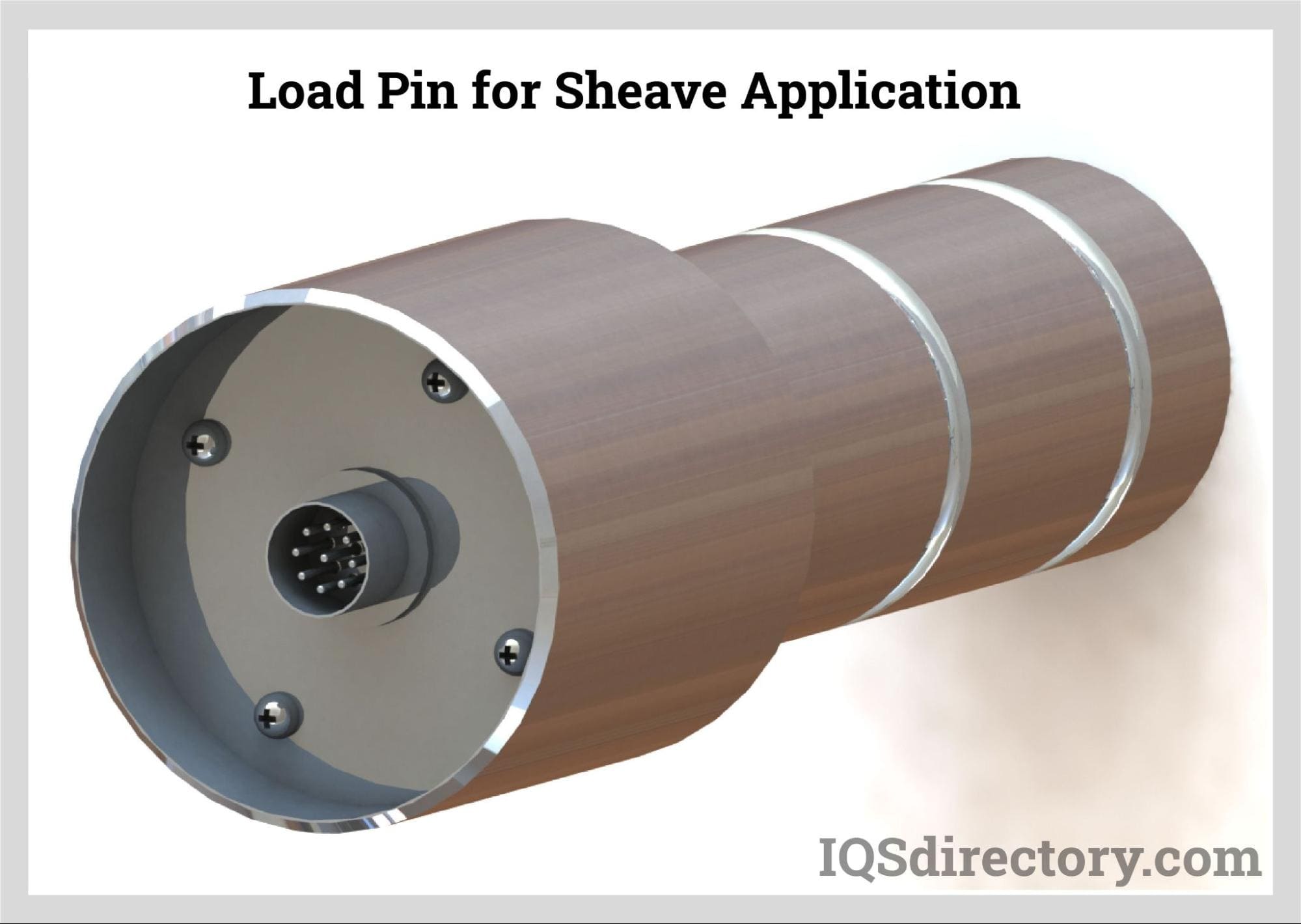
Axis of Maximum Sensitivity: Position the load sensing pin's keeper flat so it is perpendicular to the axis of maximum sensitivity at a wrap angle of one-half. In this case, the wrap angle is 105 degrees, and the angle is divided by two to get 52.5 degrees. See the specification illustration below.
Ø= Wrap Angle
T = Line Tension
P = Resultant Force on Sheave Pin
Line Tension (T): Utilize the specification picture and the following calculations to calculate the tension in a line by measuring the reaction force on the sheave:
P = 2T cos (Ø/2) or T = P ÷ 2 cos (Ø/2)
Example: For a measured sheave load of 10,000 lbs. and a wrap angle of 105. The formula: can also be used to calculate the Line Tension (T).
The bi-axial clevis pin's cross section is an example of gauge alignment. The load component Py will be sensed by the gauges designated Y, whereas the load component Px will be sensed by the gauges marked X. The resultant force P is calculated using constants (Kx, Ky) derived from calibration data* and the outputs from the two bridges as Ex and Ey.
Px = Kx Ex
Py = Ky Ey
and the resulting force P = [Px]² + [Py] squared²
Calculating the Line Tension (T) and Wrap Angle () can be done by using the following:
T = Py² + Py² ÷ 2Px and Ø = 2 inverse cosine ( P ÷ 2T)
Where P, Px, and Py are cross-talk effects corrected.
The advantage of load pin design is that it may be integrated into a system, ensuring the mechanical link between the components and providing data on applied forces. The most typical examples include clevis pins set at dead-end anchor points or the upper sheave/equalizer beam of EOT cranes, used to suspend a chain hoist to its trolley, on a fairlead sheave of a winch, at the head of a hydraulic cylinder, etc.
The design approach is based on controlling smaller load pin widths where the holding plates (flanges) and the center tool exerting the most force are separated. These smaller sizes produce deformation zones where strain gauges will be installed to assure accuracy and repeatability by ensuring sufficient strain concentration.
The mechanical resistance of the load pin is determined by these smaller sizes, which explains why a load pin cannot always replace a simple shaft because doing so would necessitate increasing the diameter. Instead, aeronautic-grade steels' high resistance level makes up for this mechanical change.
The safety coefficient of the clevis pin is defined by the load pin diameter, reduced diameters, and size of strain gauge pockets to reach the neutral fiber of the pin and concentrate the required strain:
The maximum overload for which we promise the load pin won't permanently distort is known as the permissible overload ("0" offset).
Strain limitation on the various shaft components serves as the foundation for the design requirements (the most critical being those parts in contact with the holding plates that are generally thinner than the central tool). For "FORCE" load pins, the range must stay between 150 and 200 N/mm2; for "HOIST" load pins, the range must be between 100 and 120 N/mm2; and for "LIFT" execution, a strain of about 50 N/mm2 is the target. If the working span of the pin is greater than those strain values, the shortfall of the span is made up of a larger diameter.
These design requirements ensure the mechanical and fatigue resilience of the load pin and the mechanical mounting supported by the load pin. In any event, aeronautic-grade steels with 1150 to 1350 Mpa (or N/mm²) are utilized to comprehend the well-known safety aspects.
The accuracy of the load pin is affected by various circumstances. First, if the load pin diameter is too close to the size of its active span, its accuracy performance will be poor (>3%). This low accuracy performance is due to the ratio diameter/operation span (load pin supports and deformation zone). Good decoupling is essential because if the holding plates make contact with the central tool (or sheave in hoisting applications), they will cause friction that will increase uncertainty, cause non-repeatability problems, and, in extreme cases, prevent the signal from returning to "0". After all, the releasing strains will not be able to be applied to the load pin due to friction (the central tool/sheave will remain blocked in the loaded position). There should be air gaps of at least 0.5 to 1
A load pin is designed to move with just one effort. When a force is introduced at an angle to the operating direction, the output signal is greatly reduced for any applied force that remains constant once the angle exceeds 10°. The reduction becomes even greater as the angle increases. For example, when the wire rope is wrapped around a sheave at an angle of 180°, the load pin will be acting in the direction of both wire rope falls; in the event of a 90° wrap angle configuration, the load pin will be operating at a 45° angle from both wire rope falls. For designs where the force direction is continually changing, it is also possible to use double-direction load pins (X and Y).
Thus, the pin diameter decreased, and the span of the mechanical components retaining and applying stresses to the pin affected the clevis pin's sensitivity (output signal). The "FORCE" design will produce between 1.5 and 2 mV/V, the "HOIST" design about 1 mV/V, and the "LIFT" version about 0.5 mV/V. But it also relies on how the load pin is mounted. Half-moon components that support and exert force on the pin will produce a particular sensitivity. However, a different sensitivity will be produced by mounting the pin diameter entirely. The span of the matching mounting, as well as the hardness of the material holding the pin and exerting stresses on it, both have an impact on load pin sensitivity.
It becomes clear that a single live calibration on a live mounting can produce the true image of applied efforts with the matching output signal by combining the mechanical mounting with the design and hardness of the material utilized. Any laboratory calibration will be more of a pre-calibration with its associated uncertainty than a calibration on a live mounting with actual stresses, even using a calibration instrument replicating identical mounting conditions.
Dimensionally, load pins as small as 7 mm in diameter can be made, and there is no upper limit; a load pin with a diameter ranging from 360 to 480 mm has already been constructed. By following a detailed examination of the application, nominal capacities between 2000N (0.2t) and 30MN (3000t) and even beyond can be created. For most applications, external bonding of strain gauges is used (models 5000-5300-5600 with visible pocket covers). In contrast, internal bonding of strain gauges (design 5050) is reserved for submerged/subaerial requirements (up to -5000m and more), high-pressure applications (up to 700 bars), or ATEX Ex d requirements (explosion-proof).
In terms of output signals, load pins can be fitted with inbuilt amplifiers for the following signals in addition to the conventional mV/V output: 4-20mA, 0-10V (and derived), RS485, Modbus, and CAN. In addition, analog amplifiers can be tuned to allow overloads without signal saturation using a range from "0" to nominal capacity or any other capacity.
Load pins are a type of load cell that are used as replacements for clevis, sheave, pivot, normal shaft, and equalizer pins. They are exceptionally reliable and have capacities of over 500,000 pounds (2224.11 kilonewtons).
Load pins have a bored center that contains force measuring strain gauges that measure the change in the electrical signal caused by applied force.
Load pins are used in any application that has a repeatable load path. They are beneficial to several industries, including agriculture, chemical processing, energy production, and marine cargo and port shipping operations.
Although there are standard types of load pins, manufacturers work with customers to create custom load pins for unique and special applications.
Interface load pins are machined using high tensile strength stainless steel that can be used in environments that are exposed to harsh environmental conditions.

Force sensors are transducers that transform mechanical input forces like weight, tension, compression, torque, strain, stress, or pressure into an electrical output signal whose value can be used to...
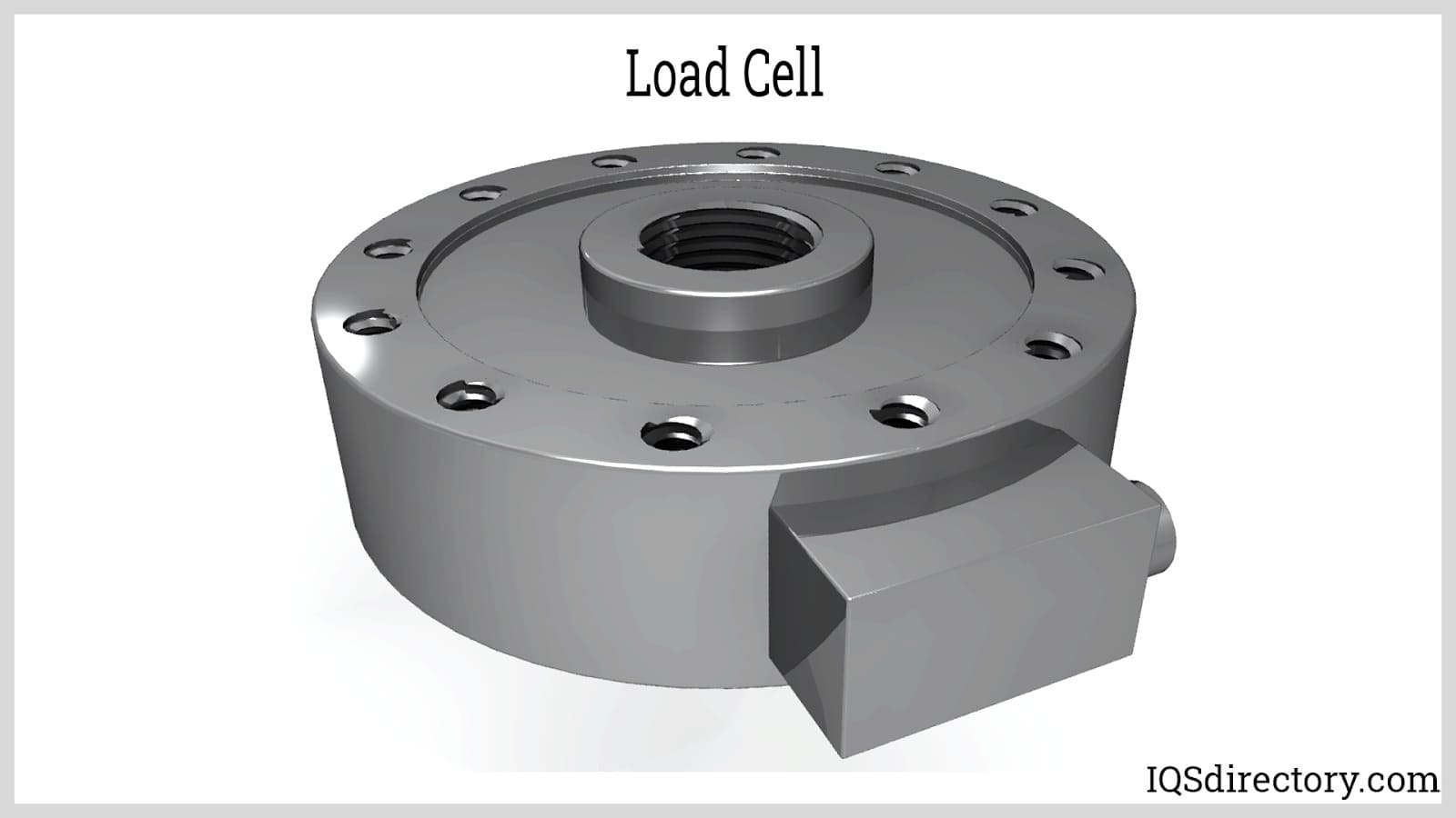
A load cell is a transducer which converts mechanical energy (tensile and compressive forces) into electrical signals. There are different transducer operating principles that can be utilized to convert forces...
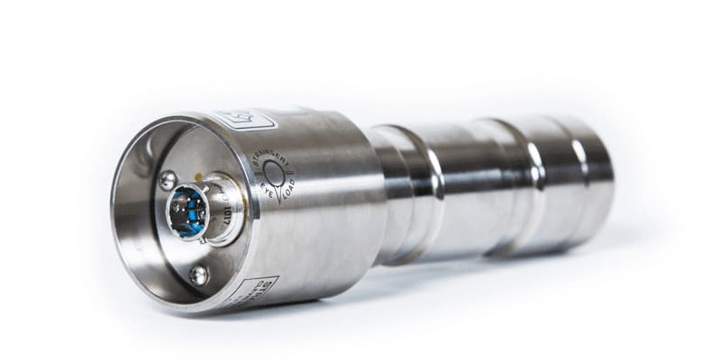
A load pin is a sensor utilized to measure force or weight in various research, control, measurement and testing applications. The load pin force sensor converts a force into an electrical signal. The load pins provide...
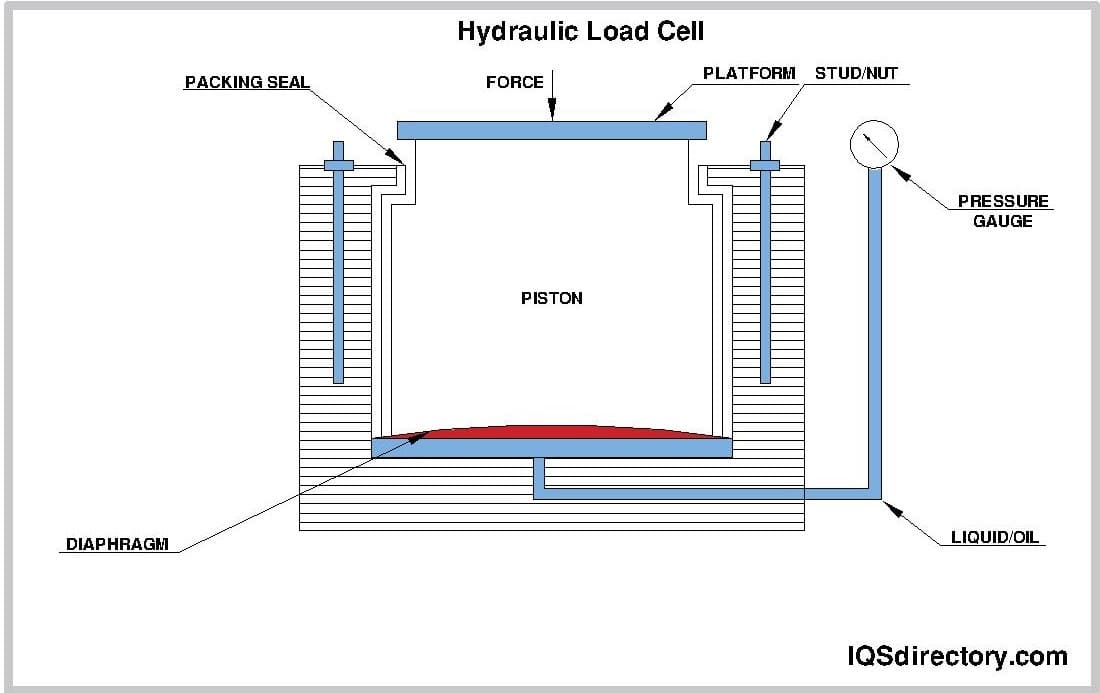
At the heart of every weighing device is a sensor called a load cell. When an item is put on a load cell, it senses the force of the gravitational pull of the weight, which an electronic circuit processes to display...
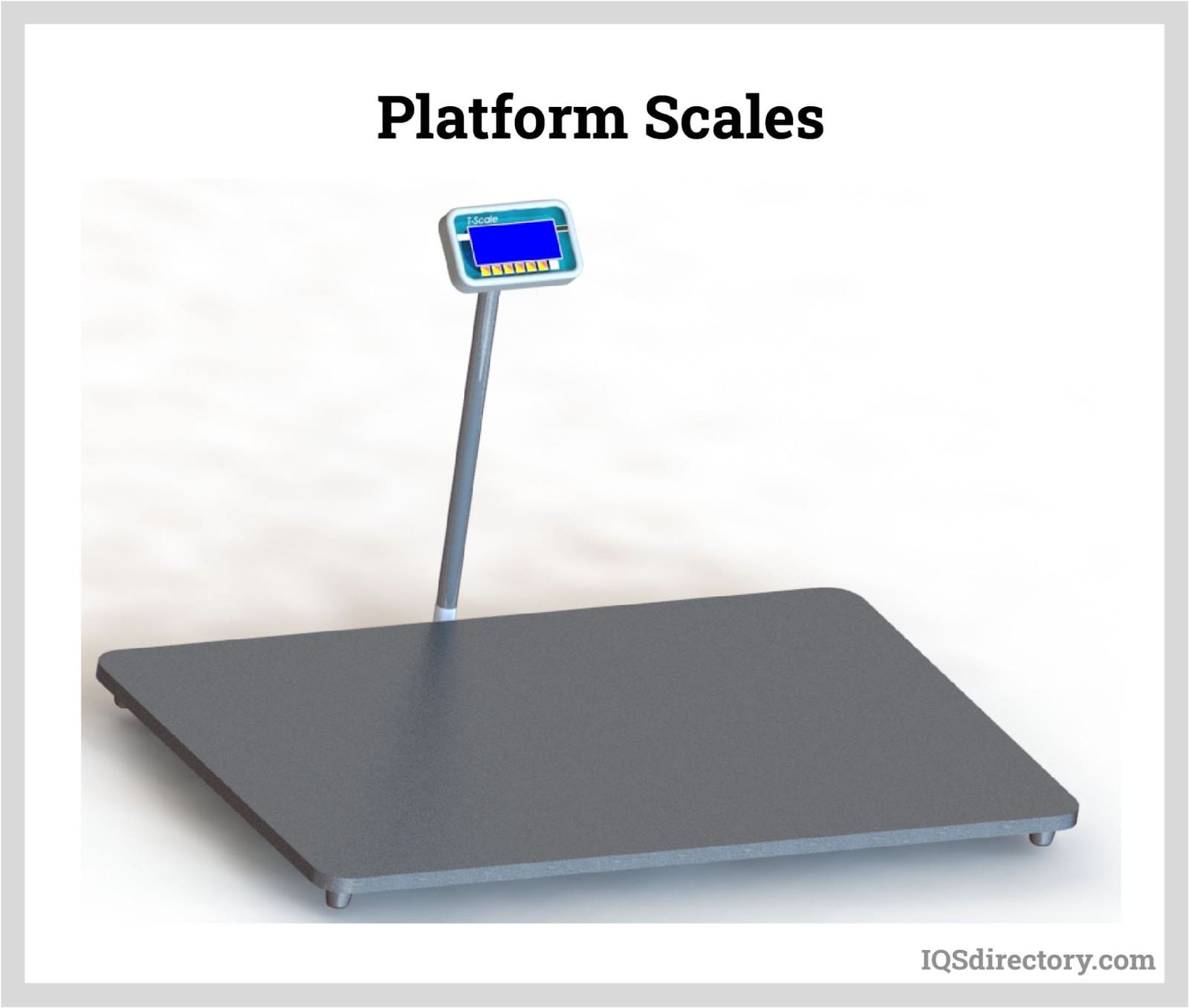
A platform scale is a scale that measures the weight of objects loaded on a flat platform. The function of the platform is to transmit the weight of the object to the internal measuring device and to support the object during weighing...