Force Sensors
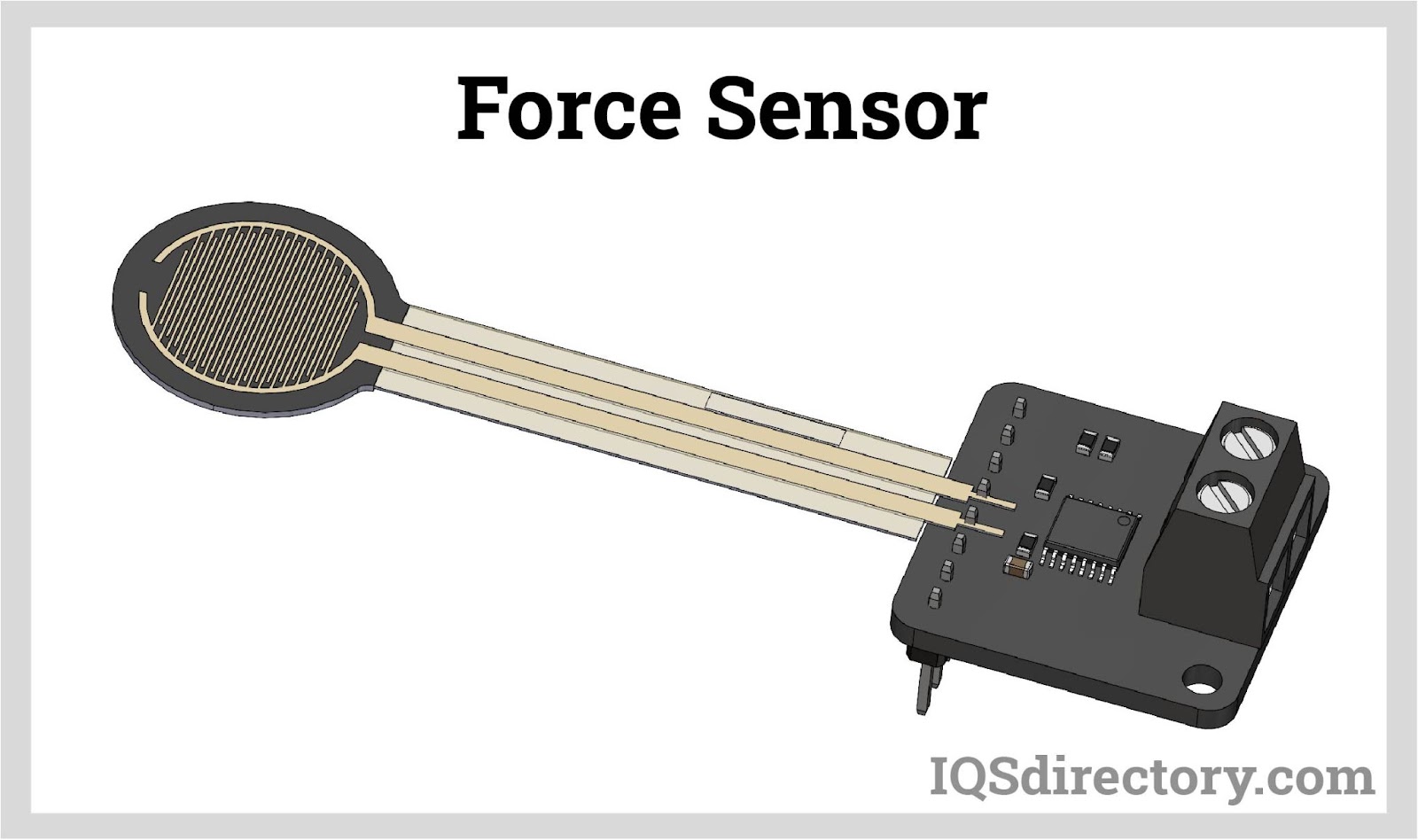
Force sensors are transducers that transform mechanical input forces like weight, tension, compression, torque, strain, stress, or pressure into an electrical output signal whose value can be used to...
Please fill out the following form to submit a Request for Quote to any of the following companies listed on
This Article takes an In-depth look at Load Cells
You will learn more about topics such as:
A load cell is a specialized transducer engineered to transform different types of forces—including tension, compression, pressure, and torque—into electrical signals or outputs. When an item is placed on a load cell, it detects the force exerted by the item's weight, attributable to gravity. This exerted force is processed through an electronic circuit and displayed as interpretable data. Load cells serve as exact mechanical transducers, offering precise measurements and readings.
A force transducer functions as a device that translates an applied force into an electrical signal, which can then be measured and standardized digitally. As the applied force intensifies, the electrical output produced by the transducer or load cell rises in proportion.
Load cells are highly accurate instruments designed for precise weight measurement. Their capability to accurately gauge both light items, like a needle, and heavy machinery, such as a drilling rig, demonstrates their adaptability and precision.
The worldwide standard unit for weight measurement is kilograms (kg). Load cells conform to this metric but also record in newtons (N), reflecting the force a mass produces under standard gravity. One kilogram equates to 9.8 newtons. To ensure precise readings, load cell measurements can be conveyed in newtons (N), kilonewtons (kN), or meganewtons (MN).
Load cells measure weight through a mechanism that includes a spring, typically made of steel or aluminum, and a strain gauge. The spring is highly durable and minimally elastic, ensuring it accurately responds to even the smallest loads.
Strain gauges are tiny devices designed to measure strain by transforming internal deformations into electrical signals. They can detect weight, force, tension, or strain with precision. A strain gauge typically consists of an electrical conductor attached to a film. As the film deforms—lengthening under tension or contracting when compressed—the conductor’s resistance changes. When the film stretches, the resistance increases, while it decreases when the film contracts. This variation in resistance is what a load cell converts into digital readings. Additionally, piezoelectric sensors can also be used; these electroacoustic transducers convert mechanical stress into electrical charges from various materials.
Load cells come with various output types, including analog voltage, current, frequency, switch or alarm, serial, and parallel. Basic load cells typically feature four gauges, while more advanced designs, like Wheatstone bridges, can incorporate up to thirty gauges. Generally, a higher number of gauges in a load cell results in increased measurement sensitivity.
When assessing a load cell's capacity, manufacturers consider the force values, the dynamics of the system, the impact of positioning the transducer within the force path, and the maximum additional loads the load cell can withstand.
For optimal performance of a load cell, it's essential that all loads or forces are directed precisely through it. Accurate readings depend on proper alignment and directionality. Key physical considerations include size, mounting or framing, accuracy requirements, vibrations, and environmental conditions. Evaluating these factors ensures the load cell delivers accurate and reliable measurements.
Load cells are classified into four accuracy classes: A, B, C, and D. Class A represents the highest level of accuracy, with the greatest number of verification intervals within its maximum range, while Class D denotes the lowest accuracy. These classifications and standard symbols for load cells were established by the International Organization of Legal Metrology (OIML) and the National Institute of Standards and Technology (NIST) of the United States Department of Commerce.
The measuring ranges for load cells are expressed using standardized symbols as follows:
The OIML mandates that certified load cells include specific information, such as their capacity, accuracy class, intended application, temperature range, and humidity rating, for proper identification.
Load cells can be categorized by their output signal or their method for detecting weight. In all cases, load cells are methods for measuring mechanical force and turning the measurements into digital values to be read and recorded.
Hydraulic load cells measure weight by detecting changes in pressure within an internal fluid. In a diaphragm hydraulic force sensor, the applied load compresses fluid in a confined elastomeric diaphragm chamber via a loading head and piston. As the force increases, the pressure on the fluid also rises. This output remains linear and is not influenced by the volume of fluid or its temperature.
Pneumatic load cells function based on a force balance principle and feature multiple dampening chambers to ensure precise measurements. They consist of an elastic diaphragm connected to a platform surface. When an object is placed on the load cell, pressurized air or gas is used to counterbalance the object's weight. The amount of air required to achieve this balance indicates the weight of the object.
Pneumatic load cells are ideal for industries that require precise measurement of small weights while prioritizing cleanliness and safety. These load cells are explosion-proof, resistant to temperature fluctuations, and free from any fluids that could contaminate processes in the event of a diaphragm rupture.
Strain gauge load cells are among the most widely used load cells, capable of measuring forces ranging from 5 N to over 50 MN. These load cells feature high-resolution digital indicators and adhere to optimal force transfer standards. Operating as transducers, strain gauge load cells alter their electrical resistance in response to stress or strain, with the resistance directly proportional to the applied strain. This ensures that the measurements from strain gauge load cells are linear and can be accurately converted into force and weight values.
Canister load cells are compact, cost-effective devices designed for both single and multiple weighing applications. These load cells are hermetically sealed and water-resistant, ensuring durability in harsh environments. With their robust construction, canister load cells excel in axial compression applications and are well-suited for measuring various capacities, including tanks, hoppers, and vehicles.
Compression load cells use a strain gauge to measure pushing forces along a single axis, with these forces being recorded as negative values. They are ideal for applications with limited space and offer exceptional long-term stability.
Compression load cells use a strain gauge to measure pushing forces along a single axis, with these forces being recorded as negative values. They are ideal for applications with limited space and offer exceptional long-term stability.
Force sensors utilize strain gauges to measure push-pull forces and flow. Unlike load cells, which measure forces in a single direction, force sensors can detect loads in all directions. The installation of these sensors is not influenced by Earth's gravitational force.
Pressure sensors are transducers that function similarly to load cells, measuring pressure, applied force, and strain in applications such as gas pressure, altitude, and liquid pressure. These sensors often utilize piezoelectric technology.
Piezoelectric crystal force transducers are employed to measure forces applied to crystalline materials. When force is exerted on a crystal, it generates an electrical charge. The piezoelectric force transducer, equipped with a charge amplifier, detects this charge and converts it into a digital signal for precise measurement.
Miniature load cells are compact compression load cells designed for high-capacity applications in tight spaces. With diameters as small as 51 mm (2 inches), they are ideal for use in test benches, industrial weighing, and prototypes. These load cells are available in miniature or subminiature sizes and feature twist-lock connectors and metric cable connections, with load capacities ranging from 0 to 100 N up to 50,000 N.
Thru-hole load cells, often referred to as donut load cells due to their shape, are designed to measure compressive forces. These load cells are characterized by their smooth, round form with a central hole that accommodates parts or bolts. They are commonly used in oil and gas pumps.
A straight block of material is secured at one end, with the other end bearing the load. Bending beam load cells, also known as bending load cells, are commonly used in industrial weighing applications, such as industrial floor scales and for weighing tanks, silos, and onboard vehicles. These load cells, which are typically made from aluminum alloys, have capacities ranging from 1 to 500 kg and are designed for low-capacity measurements.
Capacitive load cells measure weight using capacitance, which is the ability to store electrical charge. These sensors consist of two flat, parallel plates. When a voltage is applied, it creates an electrical field between the plates, storing charge. The capacitance, or the amount of charge stored, indicates the distance between the plates. As a load is applied, the distance between the plates decreases, and this change in capacitance is used to calculate the weight.
Capacitive load cells come in two types: low and mid.
Low-capacity transducers are compact devices used in medical testing equipment, wind tunnel sensors, and weight counting machines. They are designed to measure weights ranging from 0.9 ounces to 150 pounds, making them ideal for residential and retail applications.
Mid-capacity transducers are designed to measure weights ranging from 200 to 20,000 pounds with high accuracy. They are particularly suited for industrial and manufacturing settings. Typical applications include industrial scales, truck weighing systems, bolt force measurement machines, and platform scales.
Micro load cells are resistive sensors that operate based on the principle of zero piezo-resistivity. When a load, force, or stress is applied to the sensor, its resistance changes. This variation in resistance results in a change in output voltage, reflecting the altered input voltage.
Multi-axis load cells are engineered to measure multiple forces simultaneously with a single unit. They feature multiple bridges that accurately measure force from one direction while minimizing or eliminating cross-talk from other forces or moments.
High-capacity load cells are designed to measure extreme loads, such as those exerted by mine roofs or rocket thrust forces. These load cells are incorporated into various machines, systems, and instruments and are characterized by their small, lightweight, and compact design. Custom-engineered to meet specific application requirements, high-capacity load cells may need to be integrated into existing mechanisms.
Specialty transducers are designed for use in extreme environments such as underwater or in outer space. They are capable of measuring a wide range of parameters, including compression, tension, pressure, and capacity, among others.
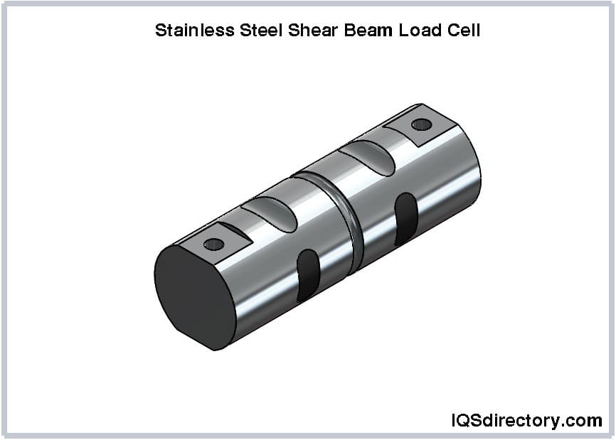
Pin load cells are equipped with load-measuring pins, or load pins, that detect applied force through strain gauges placed within a small bore running through the center of the load cell. They are commonly used in anchors, shackles, sheaves, bearing blocks, and pivots. These load cells perform effectively underwater due to their protective pin design and construction from cable and stainless steel, featuring hermetically sealed end caps.
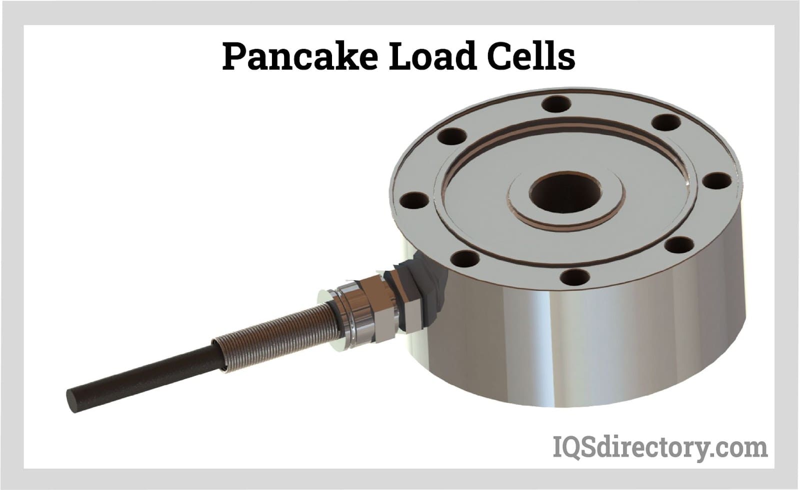
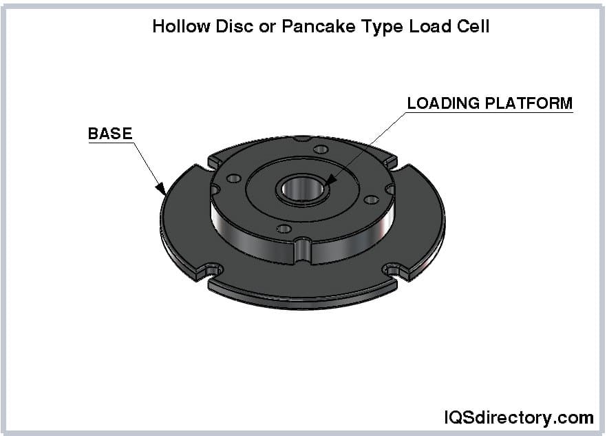
Pancake load cells are versatile devices suitable for both tension and compression measurements. They are ideal for materials and component fatigue testing, as well as for precise axial force measurements where a high-accuracy, low-profile solution is required. These load cells feature female threads in the center and multiple mounting holes around the outer ring. They can measure loads ranging from 50 lbs to one million lbs.
Dynamometer load cells, or dynos, are used to measure force, torque, and power. When combined with load cell sensing technology, they form a dyno load cell, which is specifically designed to measure engine power output. Due to their high cost, dyno load cells are typically used only when absolutely necessary.
Single point load cells feature a single operating cell and are commonly used in individual device applications, such as supermarket scales.
S Beam load cells are bending beam load cells designed for weighing applications up to 50 lbs or 22 kg. They contain a metal spring element that deforms under applied force or weight. The strain gauge measures the fractional change in the length of this deformation. S Beam load cells are commonly used in scales and tension measurement applications.
S beam load cells are favored for their precision, affordability, and ease of installation. They are designed for inline applications and are sensitive to external loads and torque. For optimal performance, S beam load cells need to be properly centered on the load and aligned with the correct direction.
Multi-axis load cells can measure tension, compression, and torque in all directions. Equipped with multiple strain gauge bridges, they accurately measure forces and torque in a single direction while minimizing interference from forces applied in other directions. These load cells help save space and reduce assembly and installation time.
The Wheatstone bridge, developed during the first industrial revolution by Charles Wheatstone, is based on an initial design by Samuel Hunter Christie. Essentially, it is an electrical circuit used to measure or compare the resistance of a resistor by balancing the two legs of the bridge. The circuit comprises four arms arranged in a quadrilateral shape with points labeled A, B, C, and D.
There are various bridge configurations, with the simplest design featuring two known resistors, one variable resistor, and one resistor of unknown value. The circuit includes an electromotive force (EMF) source and a galvanometer. The galvanometer is connected between arms B and D, while the EMF source is connected between arms A and C.
The Wheatstone bridge principle relies on the concept of null deflection. When the ratios of the resistances in the bridge arms are equal, no current flows through the galvanometer. If the galvanometer shows zero current, the bridge is in a balanced state, meaning there is no voltage difference between points B and D.
Wheatstone bridges provide greater accuracy than ammeters and voltmeters, delivering more precise results. They are capable of measuring temperature variations, strain, pressure, and changes in incident light.
The output from a load cell is typically measured in millivolts per volt (mV/V), which represents the excitation signal generated by the strain gauge. Key factors affecting a load cell’s readings include the excitation voltage, the strain gauge resistance in each leg, and the bridge resistance. The primary difference between analog and digital load cells lies in how the Wheatstone bridge output signal is processed.
Analog load cells use an analog-to-digital converter (ADC) to enable the radio frequency identification (RFID) chip to wirelessly transmit collected data to a reader. To transmit their readings, these load cells need an additional electrical circuit. They take measurements from just one cell in the Wheatstone bridge rather than all of them. Analog load cells provide continuous, real-time information.
In a load cell, the strain gauge initially produces an analog electrical voltage. In digital load cells, these signals are converted to digital format. This process requires two to six volts of energy, making digital load cells more robust than analog ones. Digital load cells transmit data from each cell in the Wheatstone bridge using binary code, which is resistant to external interference, electromagnetic disturbances, and temperature fluctuations.
Digital load cells capture and record data multiple times per second, accurately measuring hundreds of loads in just moments. This high-speed data acquisition makes digital load cells essential for complex and intricate applications.
Ingress Protection (IP) is an international standard developed by the International Electrotechnical Commission (IEC) under standard 60529. This rating system indicates the level of protection a load cell has against dust, dirt, solid objects, and liquids. The IP rating consists of two digits: the first digit represents protection against solids, ranging from 0 to 6, and the second digit represents protection against liquids, ranging from 0 to 8. A higher number in both cases signifies better protection, with the highest numbers indicating total protection.
The chart below details the various IP ratings and their corresponding meanings. The IP rating system serves as a standard guideline for load cell manufacturers to specify the quality and sealing effectiveness of their products.
| Ingress Protection Rating Scale | |||
|---|---|---|---|
| 1st Numeral | Degree of Protection | 2nd Numeral | Degree of Protection |
| 0 | No Protection At All Against Solid Objects | 0 | No Protection At All Against The Ingress Of Water |
| 1 | Protection Against Solid Objects Greater Than 50mm In Diameter | 1 | Protected Against Fallling Water Drops |
| 2 | Protection Against Solid Objects Greater Than 12.5mm In Diameter | 2 | Protected Against Fallling Water Drops At An Angle Of Up To 15° |
| 3 | Protection Against Solid Objects Greater Than 2.5mm In Diameter | 3 | Protected Against Sprayed Water Drops At An Angle Of Up To 60° |
| 4 | Protection Against Solid Objects Greater Than 1.0mm In Diameter | 4 | Protected Against The Splashing of Water From Any Direction |
| 5 | Protected Against The Ingress Of Dust In Such An Amount That It Will Not Interfere With The Operation Of The Equipment | 5 | Protected Against Water Jets From Any Direction |
| 6 | Total Protection Against The Ingress Of Any Dust | 6 | Protected Against Powerful Water Jets From Any Direction |
| 7 | Protected Against The Ingress Of Water When Temorary Immersed Of Between 0.15 m And 1 m | ||
| 8 | Prtected Against The Ingrss Of Water When Continuously Immersed To A Specified Depth | ||
Hermetic sealing involves creating an airtight seal using materials such as plastics, epoxy resins, glass, metals, and ceramics. The concept originated with an airtight glass tube known as the Seal of Hermes, named after the Greek messenger god. Hermetically sealed load cells are highly reliable and durable. This sealing not only offers robust protection but also significantly extends the load cell's lifespan and eliminates the need for frequent cleaning.
As technology has advanced, manufacturing and production have introduced wider machines to handle a broader range of materials, increasing the need for precise tension control. Without accurate controls, distortions, errors, and defects can occur in the final products, leading to costly downtime.
ITo effectively control and monitor tension and application weight, precise, accurate, and continuous measurement of production processes is essential. Oversight devices and regulation systems need to be integrated into the production process and preset with maximum and minimum levels.
Load cells are strategically positioned in processes to capture sequential measurements and convert these readings into electrical signals. The quality of these signals delivers crucial data on stability and process effectiveness. As production demands increase, load cells have become a vital inline component.
Before installing a load cell, it is crucial to test it using a multimeter and a voltage source. Set the multimeter to Ohms to measure the resistance of the load cell's input and output leads, then compare these measurements to the values on the load cell’s calibration certificate to ensure they match. Additionally, verify the load cell’s accuracy by measuring the millivolt signal from the input leads.
A digital multimeter is employed to check a load cell’s resistance by connecting it between the positive and negative signal wires of the load cell. The measured output should match the values specified in the load cell’s datasheet. To test the input resistance, measure between the positive and negative excitation wires, ensuring that their resistance values are equal.
Several factors can cause fluctuations in load cell readings. Physical damage, such as shock loading, broken cables, short circuits, and long-term overloading, can impact performance. Additionally, environmental conditions like temperature changes, moisture, water ingress in inadequately sealed load cells, and corrosion can lead to inaccurate and flawed readings.
To identify fluctuations in a load cell, start with a visual inspection for any exterior damage, which can offer clues to the source of the issue. Next, perform a zero balance check to determine if the strain gauge has been deformed or damaged. For load cells that are not hermetically sealed, also check if the insulation has been damaged or compromised.
After ruling out exterior factors like physical and environmental damage, the next step is to check for a short circuit in the load cell. This is done by performing a bridge resistance check, which will reveal if a short circuit is present.
Zero drift occurs when a load cell's measurements fluctuate significantly even when no load is applied, and it can also happen under load conditions. Various factors can cause zero drift, including mechanical errors, fluctuations in excitation voltage, and temperature variations. To identify the cause of zero drift, a thorough examination of the entire system is required.
A crucial factor in a load cell's performance is its orientation. Improper placement can lead to negative or inaccurate readings. A common issue is installing the load cell upside down, which can be avoided by checking the load cell’s directional arrow. For instance, a tension load cell installed upside down will provide erroneous and inaccurate readings.
It's important to remember that weighing systems are delicate precision instruments that require careful handling. When moving them, take all precautions to avoid vibrations during transit. For load cells integrated into a larger system, they should be removed and replaced with placeholders until the new location is reached.
The accuracy class of a load cell indicates its maximum capacity, as the absolute measurement error is proportional to this capacity. According to OIML and NIST standards, each load cell has a rated capacity clearly marked on its label. Exceeding this rated capacity can overload the load cell and cause significant damage.
The initial signs of overload damage in a load cell are inconsistent readings. After removing the load, the load cell might not return to zero, or there may be significant shifts in the zero balance.
While it is commonly assumed that overloading a load cell by exceeding its capacity is the primary cause of damage, the reasons for overload issues can be more complex. Often, overloading can result from dropping a load, even if it is within the load cell's rated capacity, onto the system. This can create an extreme, rapid change in weight, leading to significant damage in a very short time.
While overload can be a serious issue, load cells can occasionally withstand infrequent overloads without immediate damage. However, constant or frequent overloads are akin to repeated impacts and can cause permanent damage.
Overload issues are more common in load cells with lower maximum capacities and occur more frequently than in those with higher capacities. Load cells with capacities under 50 kg can be damaged by small items, such as lightweight boxes or tools, falling onto them.
Given the critical role of load cells in processes and operations, various protective measures are designed to prevent damage from overloads. Engineers incorporate these protections into load cells, such as mechanical stops that restrict the travel distance of a load. A threaded screw, set to the load cell’s maximum capacity, limits the deflection of the load cell.
Pretensioned springs provide another method of overload protection. When the maximum load capacity is exceeded, the spring compresses and applies force to act as a mechanical stop. The wider gap width in pretensioned springs simplifies and enhances the reliability of setting the allowed load. These springs also offer excellent protection against pulse loads and accidental drops.
Load cells measure physical quantities or mass and convert force or energy into other forms, such as force, light, torque, or motion. They are employed in mechanical testing, system monitoring, and as components in industrial scales. Common applications include household scales and measurement devices used in heavy industries.
Industries that utilize load cells include:
Load cells are part of security systems, electrical weighing scales, personal scales, thermometers, machines in the defense sector, industrial automation, submarine pressure sensing, and material testing.

Force sensors are transducers that transform mechanical input forces like weight, tension, compression, torque, strain, stress, or pressure into an electrical output signal whose value can be used to...
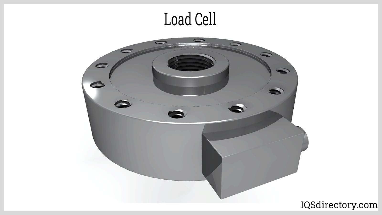
A load cell is a transducer which converts mechanical energy (tensile and compressive forces) into electrical signals. There are different transducer operating principles that can be utilized to convert forces...
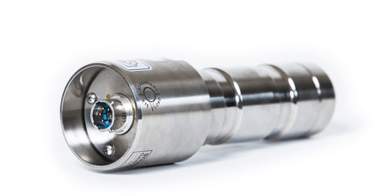
A load pin is a sensor utilized to measure force or weight in various research, control, measurement and testing applications. The load pin force sensor converts a force into an electrical signal. The load pins provide...
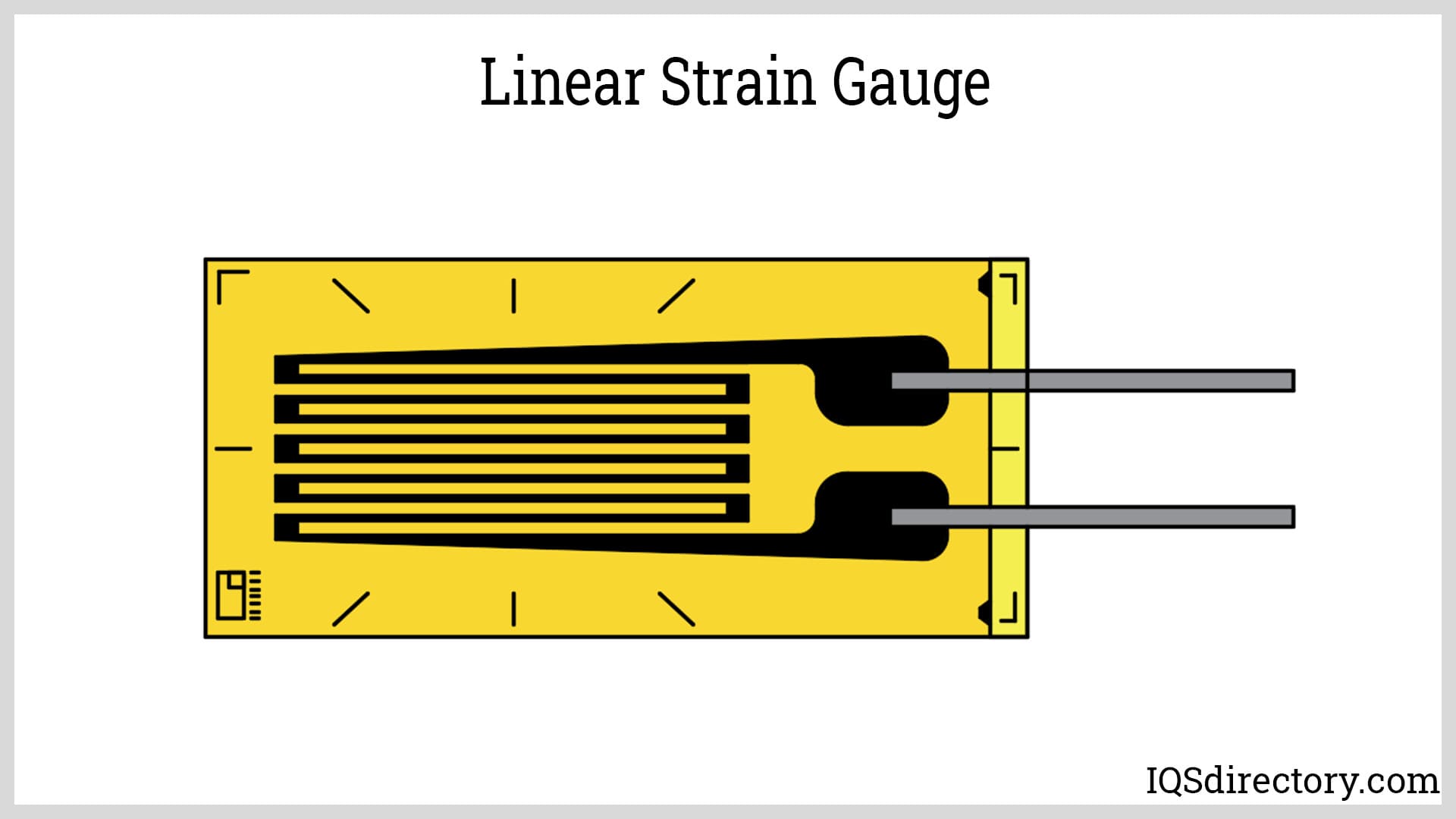
A strain gauge, or strain gage, is a sensing device used for measuring strain experienced by an object. It is made from a long, thin piece of conductor bonded to an elastic backing material called a carrier...
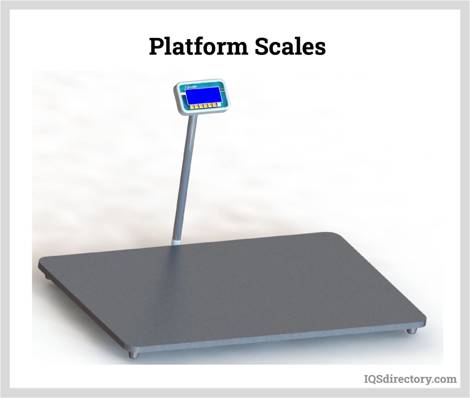
A platform scale is a scale that measures the weight of objects loaded on a flat platform. The function of the platform is to transmit the weight of the object to the internal measuring device and to support the object during weighing...