Metal Injection Molding: Processes, Advantages and Considerations
Introduction
This article takes an in-depth look at Metal Injection Molding.
Read further and learn more about topics such as:
- What is Metal Injection Molding
- Stages of a Metal Injection Molding Process
- Advantages and Disadvantages of Metal Injection Molding
- Considerations in Metal Injection Molding
- And Much More...
Chapter 1: Understanding Metal Injection Molding
Metal Injection Molding (MIM), also known as powder injection molding (PIM), is an advanced production process used to fabricate solid metal parts through the principles of injection molding technology. Initially designed for molding ceramic materials, this innovative technique was adapted in the 1970s by Raymond Wiech to accommodate metal substrates. Since the 1990s, MIM has gained significant traction as a prevalent technique in metal manufacturing.
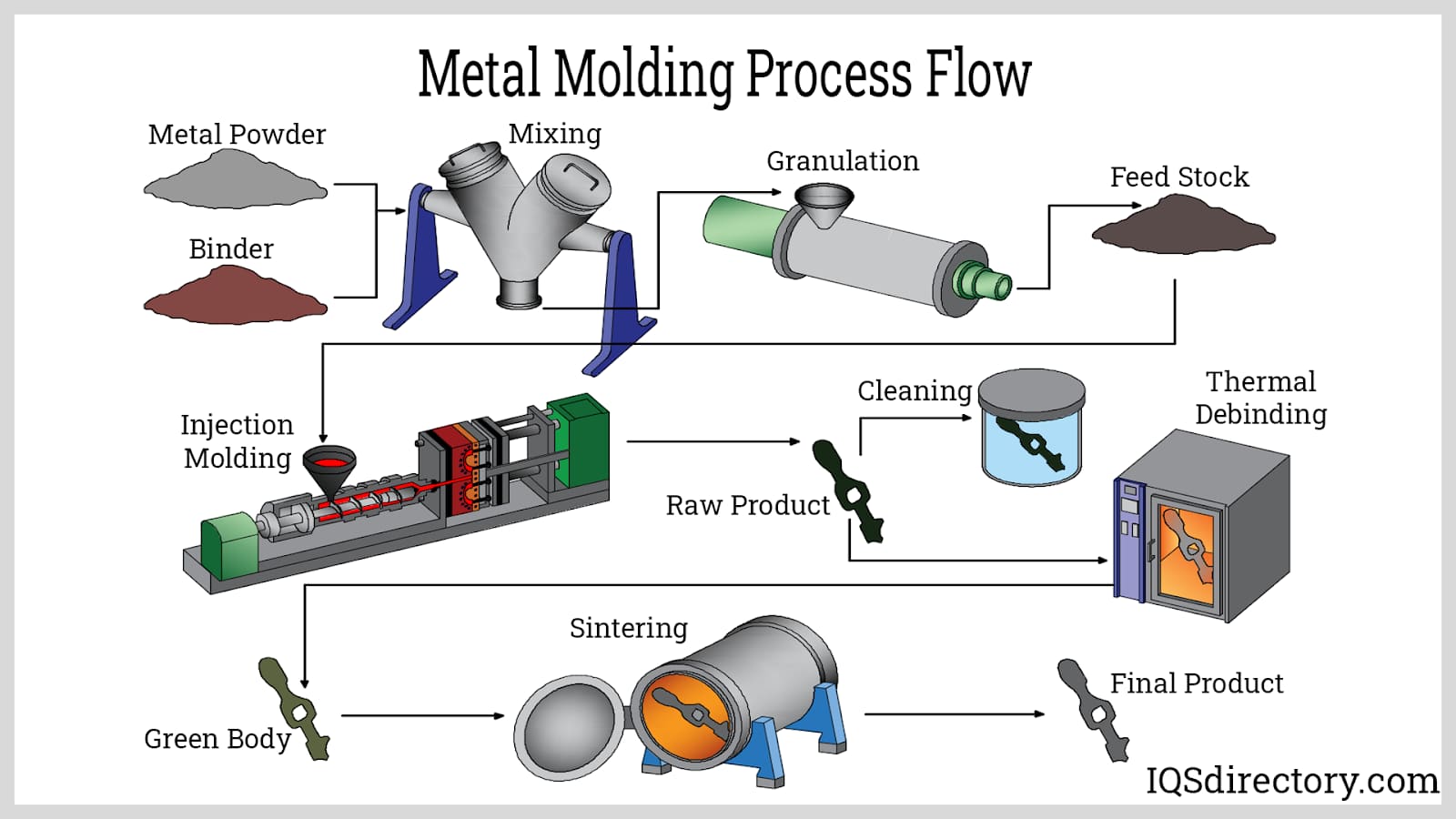
In the metal injection molding process, fine metal powders are blended with a plastic binder to produce a feedstock optimized for injection molding. This blend is melted down, formed, and then cooled using a conventional molding machine. Once the molding is complete, the parts undergo a binder extraction process followed by sintering, which removes the plastic binder and improves the density and robustness of the metal. These following steps are critical to ensure that the fabricated components meet the necessary geometry, chemical composition, and physical attributes.
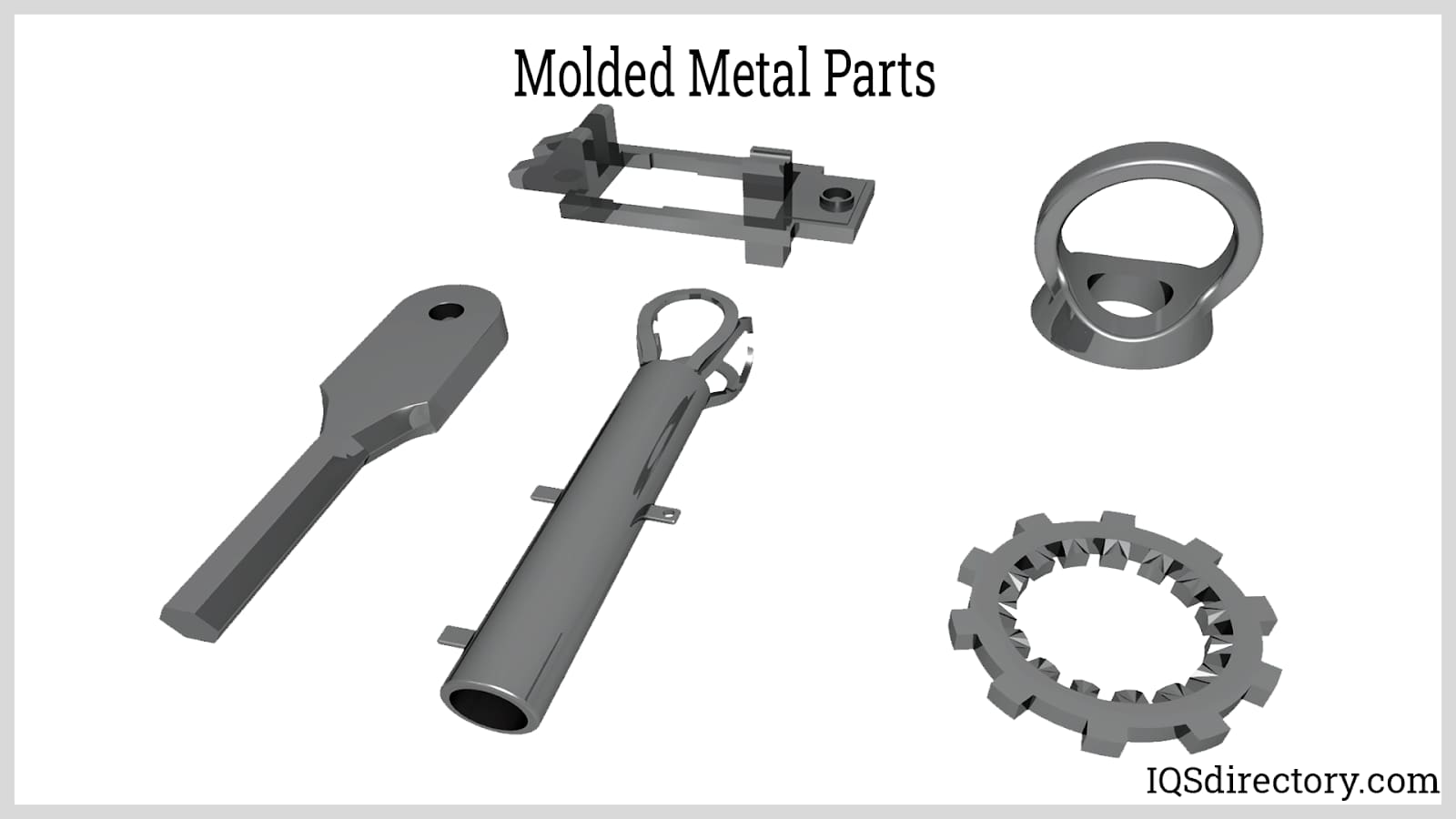
Metal injection molding is particularly beneficial for producing high volumes of compact, intricate parts with elaborate features. It facilitates exact manufacturing without requiring additional machining activities. This methodology supports a wide range of both ferrous and non-ferrous metals and is generally more economically favorable than traditional techniques like casting, forging, and machining. Components produced via MIM find applications across numerous sectors, including automotive, aerospace, electronics, telecommunications, medical, dental, sporting goods, consumer products, and defense, where precision and complexity are essential.
Chapter 2: What are the stages of the metal injection molding process?
The metal injection molding process (MIM) is a highly sophisticated manufacturing technique that enables the production of complex, precision metal components with properties comparable to those made by traditional metalworking methods. This process is increasingly favored in sectors such as the automotive, aerospace, medical device, electronics, and defense industries for its efficiency, high-quality results, and ability to reduce manufacturing costs for intricate parts. The core MIM process stages are outlined below, with each step offering unique advantages for manufacturers seeking repeatability and scalability in high-volume production.
Feedstock Mixing
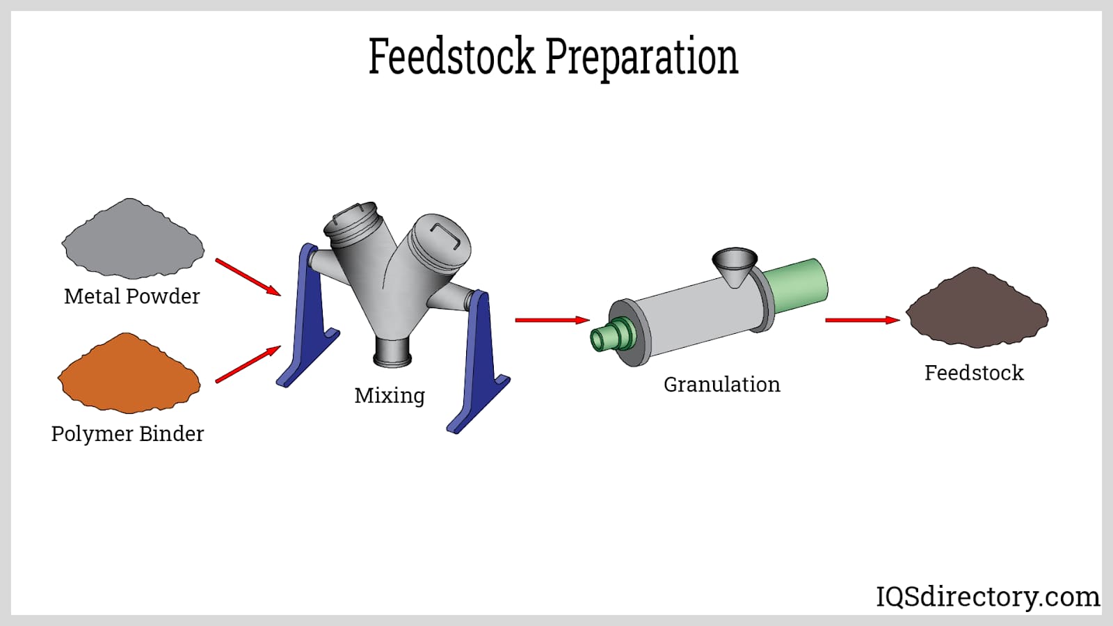
The first stage in metal injection molding is feedstock preparation. Here, fine metal powder (typically stainless steel, titanium alloys, or tool steels) is precisely mixed with a thermoplastic binder to form an intermediate material called feedstock. This uniform mixture is essential for creating MIM parts with the desired mechanical properties and dimension accuracy. The binder system in metal injection molding offers several crucial functions:
- It modifies the feedstock viscosity and significantly improves flowability, vital for consistently filling complex mold cavities and minimizing defects in advanced metallurgy applications.
- It imparts cohesion and green strength, allowing the molded component to maintain its structural integrity after de-molding and during subsequent processing steps, even after partial binder removal.
- It facilitates the clean release of delicate molded parts from high-precision MIM tooling.
The binder system often includes three functional components:
- A lubricant and plasticizer (e.g., polyethylene glycol, wax) for improved fluidity and efficient powder dispersion.
- A backbone polymer (e.g., polypropylene, polyethylene) that ensures green part stability and toughness during automated handling.
- A surfactant (e.g., stearic acid) that prevents agglomeration, ensuring optimal powder-binder interaction and feeding consistency inside the injection molding machine.
The presence of binder in the metal matrix will negatively affect performance characteristics if left behind, making complete binder removal a top priority for process quality control. Essential binder features for feedstock include:
- Water-solubility or the ability to decompose easily under mild thermal, solvent, or catalytic conditions.
- Non-reactivity with key metal powders like stainless steel, titanium, or cobalt-chrome alloys.
- Recyclability of excess or scrap material recovered from the injection molding cycle, promoting sustainability and lean manufacturing.
- Cost-effectiveness and compliance with environmental health and safety regulations.
During feedstock preparation, manufacturers use highly controlled equipment to blend fine metal powders (often around 20 microns, smaller than those used in traditional powder metallurgy) with the binder at a metal-to-binder volume ratio typically near 60:40. The resultant homogeneous mixture is granulated, cooled, and pelletized for reliable feeding into injection molding machines. This crucial step ensures lot-to-lot consistency and directly impacts the material properties, dimensional tolerances, and surface finish of finished MIM components.
Injection Molding
The injection molding step utilizes standard or specialized MIM injection molding machines to melt and inject feedstock into highly precise molds. These molds are often produced using advanced tooling technologies to replicate intricate geometries, thin walls, and fine details, making MIM ideal for small, complex parts where traditional machining would be costly or impossible. The carefully controlled conditions ensure each shot fills every mold cavity, guaranteeing repeatability and tight tolerances.
Because sintering will result in 15–25% shrinkage, MIM molds are designed with deliberate oversize to account for this dimensional reduction. The components produced at this stage are called "green parts." Green parts remain fragile but possess the shape and micro-features necessary for the finished product. After cooling within the mold, automated or manual ejection removes the part for further processing, and gating, runner, and sprue systems are trimmed away to optimize subsequent material flow analysis and minimize secondary waste.
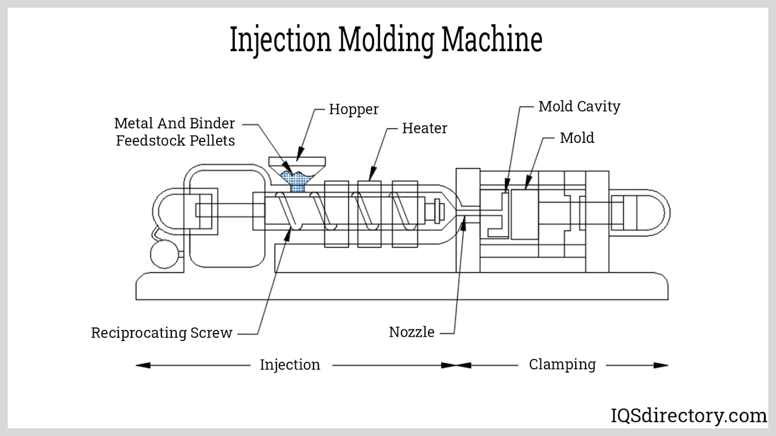
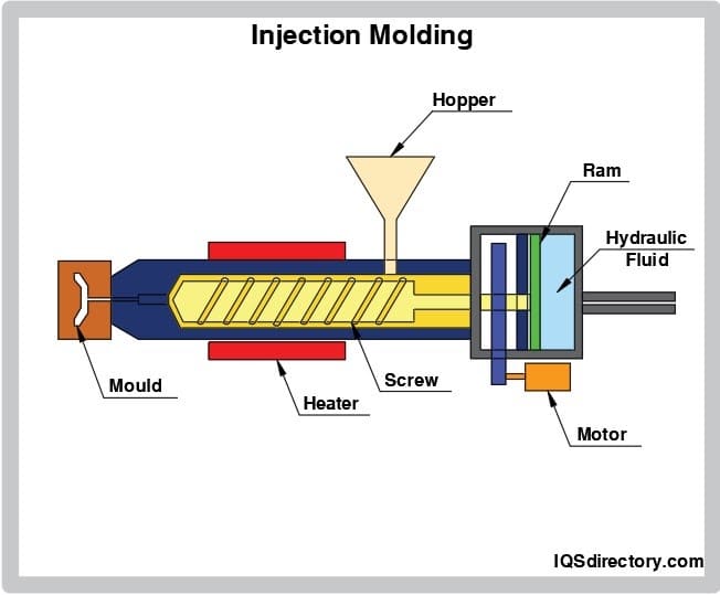
A modern injection molding machine for MIM consists of several critical subsystems:
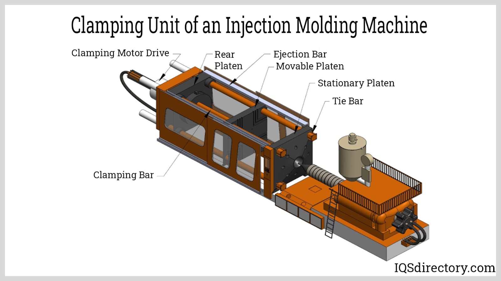
Clamping Unit
The clamping unit applies significant force to keep the mold halves tightly closed during feedstock injection and cooling. It incorporates the ejection mechanism for green parts and precisely aligns the tool during cycling, preserving dimensional accuracy critical in precision metal injection molding.
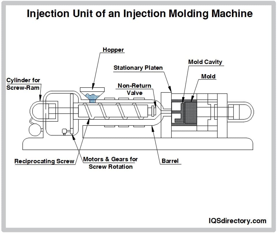
Injection Unit
The injection unit melts and injects the metal-binder feedstock into the mold cavities. Its main components include:
- Hopper: Holds and meters the feedstock pellets for controlled feeding, which supports consistency in part quality and mold fill behavior.
- Barrel: Houses the injection screw and heaters, ensuring uniform thermal distribution and optimal melting performance for the metal-polymer blend.
- Injection Screw: Mixes, conveys, and delivers molten feedstock under pressure, facilitating even distribution and the elimination of voids or short shots.
- Nozzle: Connects to the stationary mold half, ensuring clean, accurate delivery of each feedstock shot into the multi-cavity mold system.
Mold in the Molding Process
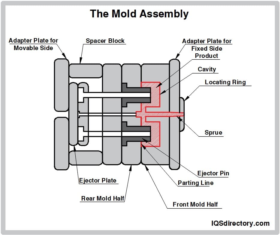
The MIM mold shapes every feedstock shot and is engineered with tight tolerances and intricate features. The stationary front half interfaces with the injection unit, and the rear half, mounted on a moving plate, opens for automated ejection. Mold design considerations, such as runner systems, multi-cavity layouts, venting for air or gas release, and coolant lines for rapid thermal cycling, all contribute to the cost-effectiveness, lead-time reduction, and high-volume scalability of the MIM process.
After the fill and cooling phases, runners, gates, and sprues containing solidified feedstock are physically trimmed, sometimes recycled to promote waste reduction. The careful mold engineering and gating strategy ensures uniform fill, preventing common MIM defects like warping, incomplete fill, or sink marks, while holding tight tolerances needed for end-use applications across critical industries.
Mold cooling and controlled venting are optimized to prevent defects and support consistent, repeatable output.
Process optimization parameters such as injection speed, clamping force, melt temperature, holding pressure, and proper cooling are critical for achieving high production yields, superior surface finish, and precision in MIM parts.
Debinding
Debinding is a crucial step in which the majority of organic binders are removed from the green part to prevent compromised density or unwanted chemical residues in the finished MIM components. The output at this stage is known as the "brown part," featuring a porous structure lighter than the final sintered part but maintaining detailed geometry. The brown part retains some binder to preserve shape and withstand gentle handling as porosity becomes a key enabler for gas or solvent migration in subsequent stages.
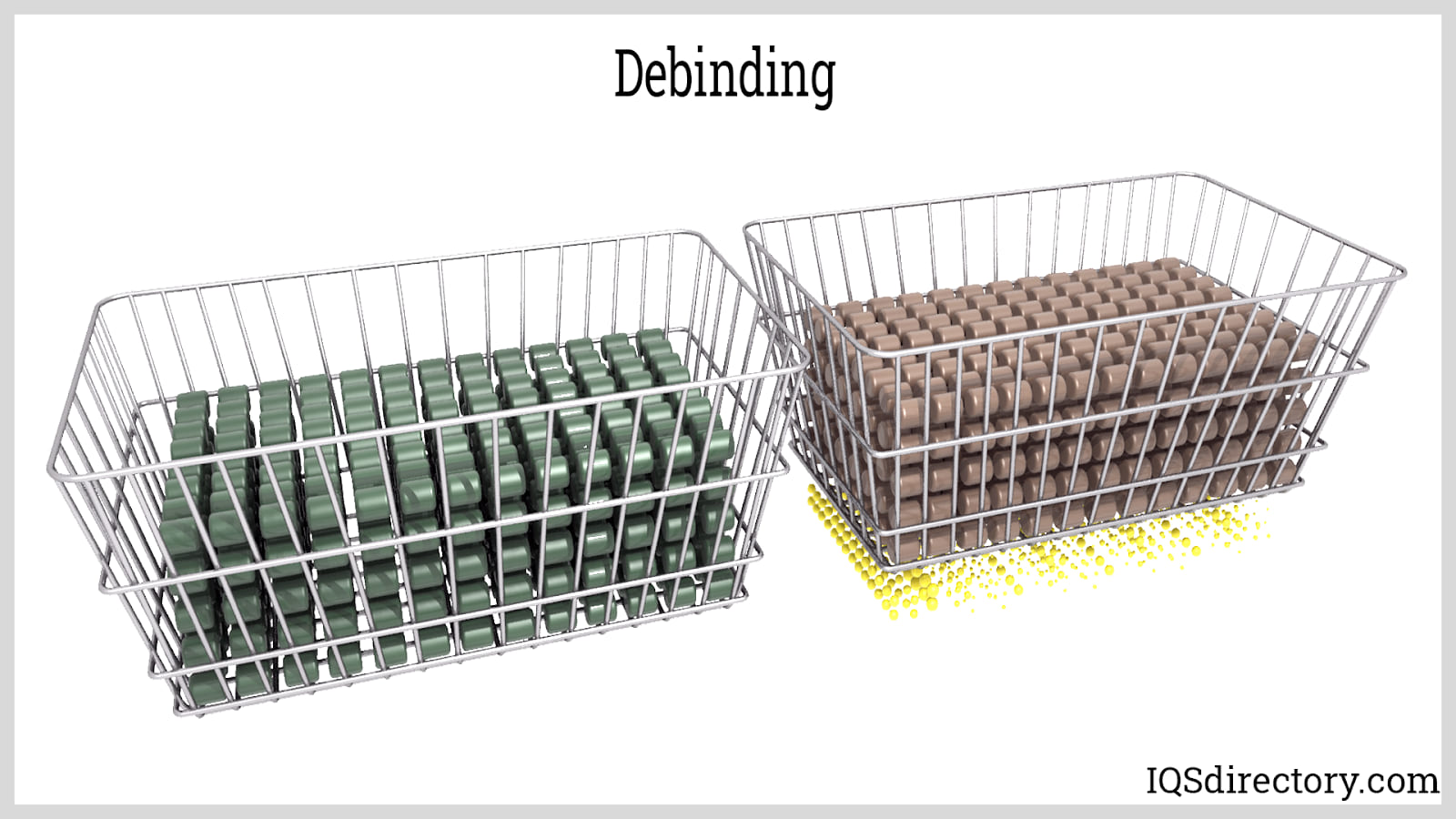
Debinding process selection—thermal, solvent, or catalytic—is tailored according to binder chemistry, production scale, part geometry, and environmental or regulatory requirements. Precision in debinding is vital to preserve green strength, prevent defects like blistering or distortion, and prepare each part for successful, efficient sintering.
Thermal Debinding
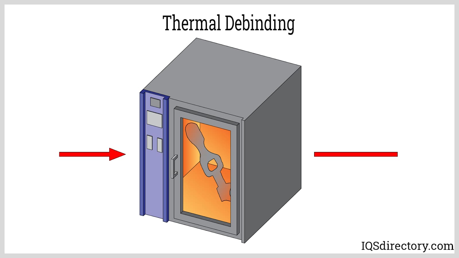
During thermal debinding, brown parts are heated in a carefully controlled furnace—often under an inert or reducing atmosphere—to gradually volatilize and remove the organic binder. Typical temperatures are aligned with binder decomposition profiles, balancing minimized part deformation, efficient binder burnout, and low risk of cracking. This method is cost-efficient in terms of equipment investment but can require extended dwell times, sometimes over 24 hours, especially for large or high-density parts.
Solvent Debinding
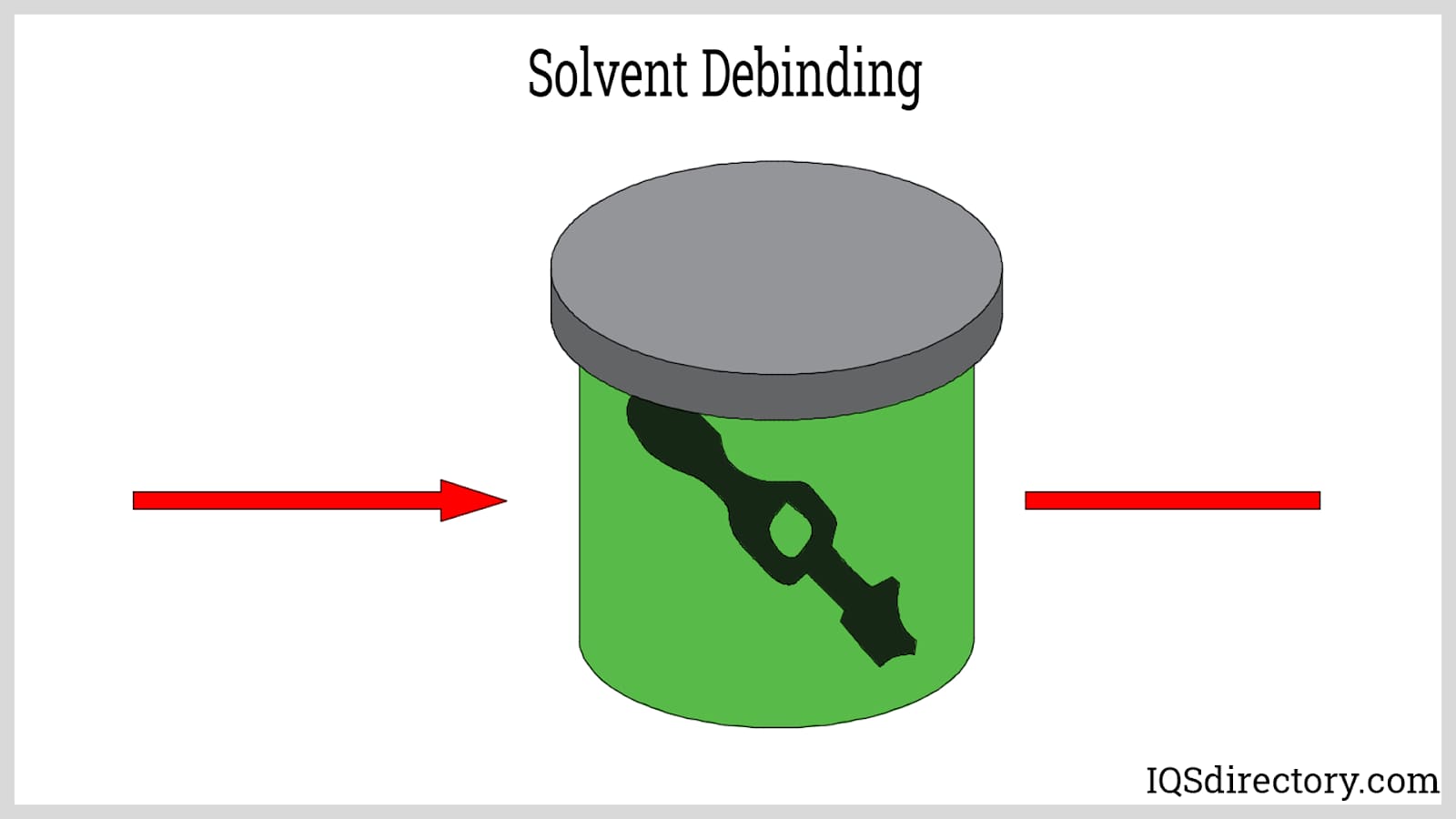
Solvent debinding immerses green parts in solvent baths specifically chosen for efficacy and environmental compliance. Common industrial solvents such as acetone, heptane, and specialized hydrocarbon blends are used, as well as water for water-soluble binders. This process, widely adopted in medical and electronics MIM production, is valued for lowering thermal load on parts and supporting faster cycle times when used in hybrid debinding strategies.
Catalytic Debinding
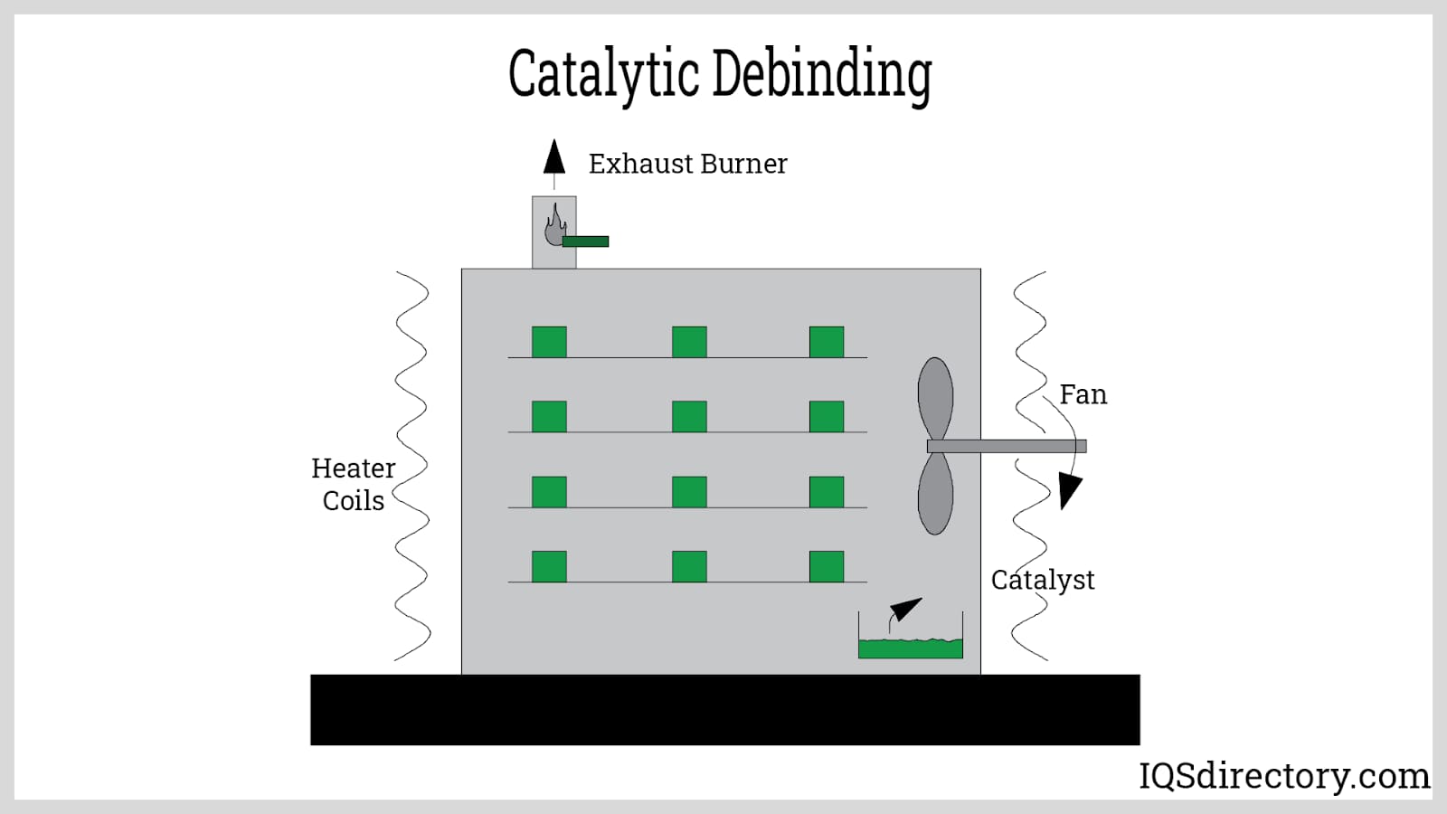
In catalytic debinding, acid gases (such as nitric or oxalic acid) selectively break down binder components. Used extensively with polyacetal-based binders, this approach enables shorter cycle times and excellent process control for high-volume or tight-tolerance applications. However, it is limited to certain binder chemistries and requires careful handling of byproduct gases and adherence to strict environmental standards.
Supercritical Fluid Debinding
Supercritical fluid debinding employs supercritical carbon dioxide or other fluids under specific pressure and temperature conditions to dissolve and extract binders efficiently. Niche yet growing in adoption, it offers cleaner, faster processing for select binder types (especially non-polar molecules like paraffin wax) with reduced defects, improved surface finish, and minimal environmental impact.
Sintering Process
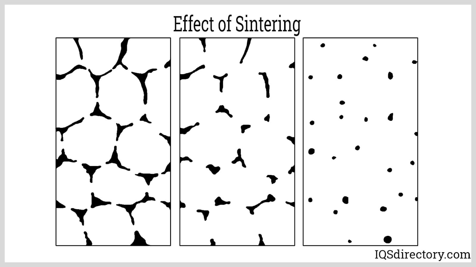
Sintering is the pivotal transformation step in the metal injection molding process—the brown part is placed in a sintering furnace under a tightly controlled atmosphere (such as argon or hydrogen) to prevent oxidation and contamination. The furnace gradually raises the temperature, often to 96–99% of the material's melting point, allowing atoms within the metal powder particles to diffuse and bond. Through this solid-state diffusion and partial melting, the part undergoes significant densification, resulting in a finished product with high mechanical performance, exceptional dimensional accuracy, and a surface finish suitable for most end-use applications in demanding industries like aerospace or medical devices.
Key outcomes of sintering metal injection molded parts include:
- Uniform densification and the elimination of interconnected pores—enabling the part to shrink uniformly to 75–85% of its molded size, as accurately predicted during design for near-net-shape manufacturing.
- Removal of all remaining organic binder traces, ensuring optimal material purity and biocompatibility in demanding environments, such as surgical instruments or dental components.
- Achievement of outstanding mechanical strength, hardness, and resistance to wear or corrosion, making MIM ideal for precision gears, structural components, and high-stress industrial fittings.
Hot Isostatic Pressing
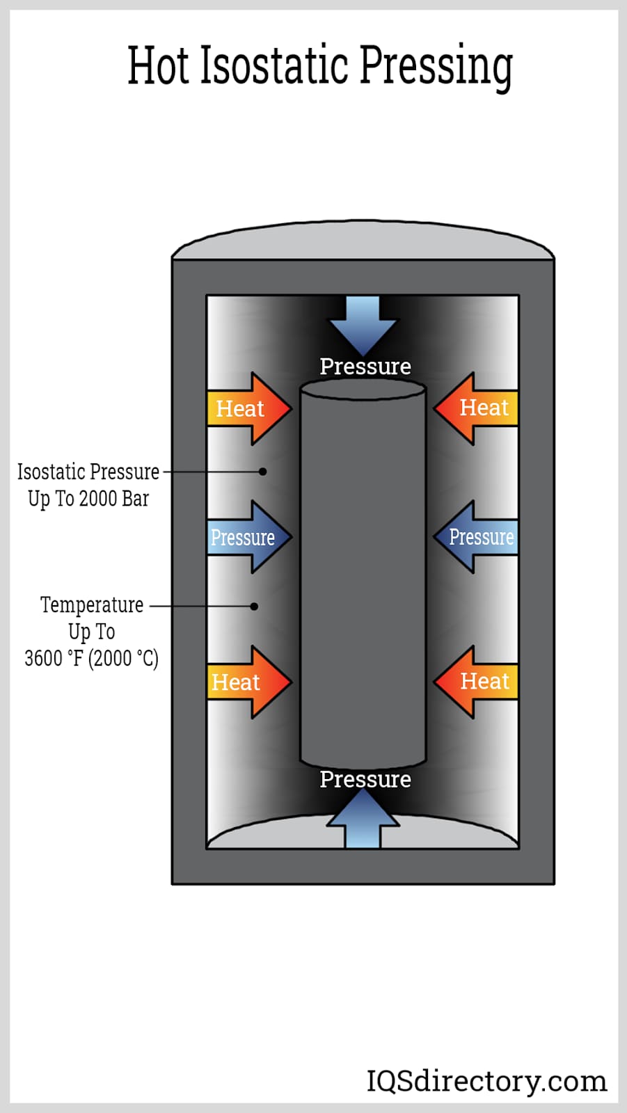
Hot Isostatic Pressing (HIP) serves as a post-sintering densification method, especially for parts requiring near 100% theoretical density or optimized microstructure for fatigue-critical or high-performance roles. In HIP, the sintered component is subjected to both elevated temperature and isotropic gas pressure within an evacuated chamber, commonly using argon or nitrogen. The synergy of heat and pressure eliminates internal voids, closes micropores, and can heal micro-cracks, substantially improving a component’s toughness, damage tolerance, and life expectancy.
Use of HIP, particularly for aerospace, medical implants, and demanding defense or industrial applications, ensures superior mechanical integrity and product reliability. Advanced MIM suppliers now offer HIP as an integrated step, aligning with customer expectations for highest quality standards and predictable, repeatable results for mission-critical components.
Leading Manufacturers and Suppliers
Choosing the right MIM supplier is essential for achieving best-in-class results tailored to your project’s requirements. Consider suppliers with extensive experience in material selection, powder metallurgy, tooling design, secondary finishing capabilities, and stringent quality assurance. Industry leaders often provide prototyping, custom alloy development, and end-to-end support, facilitating the optimization of your metal injection molding solutions for applications spanning automotive, electronics, medical, and industrial markets.
For more information on how to partner with trusted MIM manufacturers or to request a quote for your next precision metal project, explore the listing of leading companies above or consult with a technical advisor to review design, tolerancing, and application engineering options.
Chapter 3: What are the advantages and disadvantages of metal injection molding?
Metal injection molding (MIM) is an advanced manufacturing technology that combines the design flexibility of plastic injection molding with the material strength of powdered metallurgy. This section explores the key advantages and limitations of MIM to help manufacturers and engineers determine if this metalworking technique aligns with their product requirements and production goals.
Advantages of Metal Injection Molding:
- MIM can support large production quantities of metal parts with complex geometries and details. It is best suited for high-volume manufacturing of small and precision parts with tight tolerances, making it ideal for industries like medical devices, automotive, aerospace, electronics, firearms, and consumer products.
- MIM can accurately produce features such as internal and external threads, undercuts, gear teeth, slots, holes, fins, surface markings, and engravings without the need for secondary machining and fabrication processes. This reduces lead time and overall production costs.
- MIM imposes few restrictions on part design, providing exceptional design freedom to manufacture a variety of intricate or highly detailed shapes that may be impossible or cost-prohibitive with traditional metal forming methods such as die casting or CNC machining.
- MIM generates parts with superior mechanical properties. The density, strength, and hardness of MIM-produced components are generally comparable to their wrought alloy or fully dense counterparts, supporting critical applications that demand robust performance and precision engineering.
- MIM yields high-quality surface finishes as-molded, often eliminating or reducing the need for post-processing and secondary finishing. Surface roughness is typically lower than parts produced by traditional powder metallurgy or metal casting.
- MIM enables the fabrication of multi-component assemblies as a single, consolidated piece, streamlining supply chains and improving part reliability by reducing the need for joining, welding, or fasteners.
- MIM produces less material waste and scrap than subtractive processes like CNC machining, which is especially important for costly or exotic materials such as refractory metals, titanium alloys, superalloys, and specialty metals. The process typically achieves a material utilization rate of 95-98%, maximizing economic efficiency.
- MIM is more cost-effective than machining, investment casting, or stamping for medium- to high-volume production runs, particularly when complex shapes or intricate designs are required. Lower per-part costs can be achieved as production volumes scale.
-
MIM is compatible with a wide range of high-performance metals and specialty alloys, allowing product designers to choose materials for optimal corrosion resistance, wear resistance, electrical conductivity, or biocompatibility. Common materials processed through MIM include:
- Stainless Steel (e.g., 17-4 PH, 316L)
- Carbon Steel
- Copper Alloys
- Nickel Alloys
- Tungsten Alloys
- Titanium Alloys
- Cobalt-Chromium Alloys
- Iron
- Cemented Carbide
- Cermet Materials
In general, metals that are highly reactive, toxic, or prone to rapid oxidation are considered unsuitable for the MIM process. Examples include lead, magnesium, manganese, and beryllium. While some research and development efforts have explored the potential for using aluminum alloys—thanks to their relatively low melting points—aluminum MIM is not yet widely commercialized due to processing challenges such as binder compatibility and oxidation resistance.
MIM technology is especially attractive for applications requiring small, precise metal parts with intricate geometries in sectors like electronic connectors, smartphone components, dental and orthodontic appliances, industrial tools, and custom fasteners.
Disadvantages and Limitations of Metal Injection Molding:
- A MIM operation may require a high initial capital investment and elevated processing costs. This is attributed to the acquisition and operation of specialized injection molding equipment, sintering furnaces, and the necessity for precision mold tooling. The largest expenses typically arise from tool design and mold production. High returns and cost efficiencies are best realized with sustained, high production volumes.
- The cost of MIM is often prohibitive for small production runs or low-volume custom metal part orders. In such cases, other metal forming technologies like CNC machining, die casting, or additive manufacturing may offer more economical solutions.
- MIM is suited for manufacturing small to medium-sized components, typically under 100 grams. Attempting to produce larger parts can diminish mold and furnace capacity, increase overall processing time, and drive up costs, limiting the technique's scalability for oversized applications.
- The MIM process involves multiple steps—feedstock preparation, injection molding, debinding, and sintering—which require precise process control and technical expertise. This makes the manufacturing workflow comparatively complex versus other traditional and additive manufacturing processes.
When evaluating whether to use metal injection molding versus alternative metal fabrication processes, it is important to consider factors such as production volume, component size, material requirements, intended application, cost targets, and desired mechanical properties. For manufacturers or product engineers seeking to optimize design complexity, reduce material waste, and achieve excellent repeatability in the production of small, precision metal components, MIM stands out as a strategic choice within modern metal manufacturing solutions.
Chapter 4: What considerations should be taken into account in metal injection molding?
When designing for metal injection molding, consider the following factors:
Ejector Marks
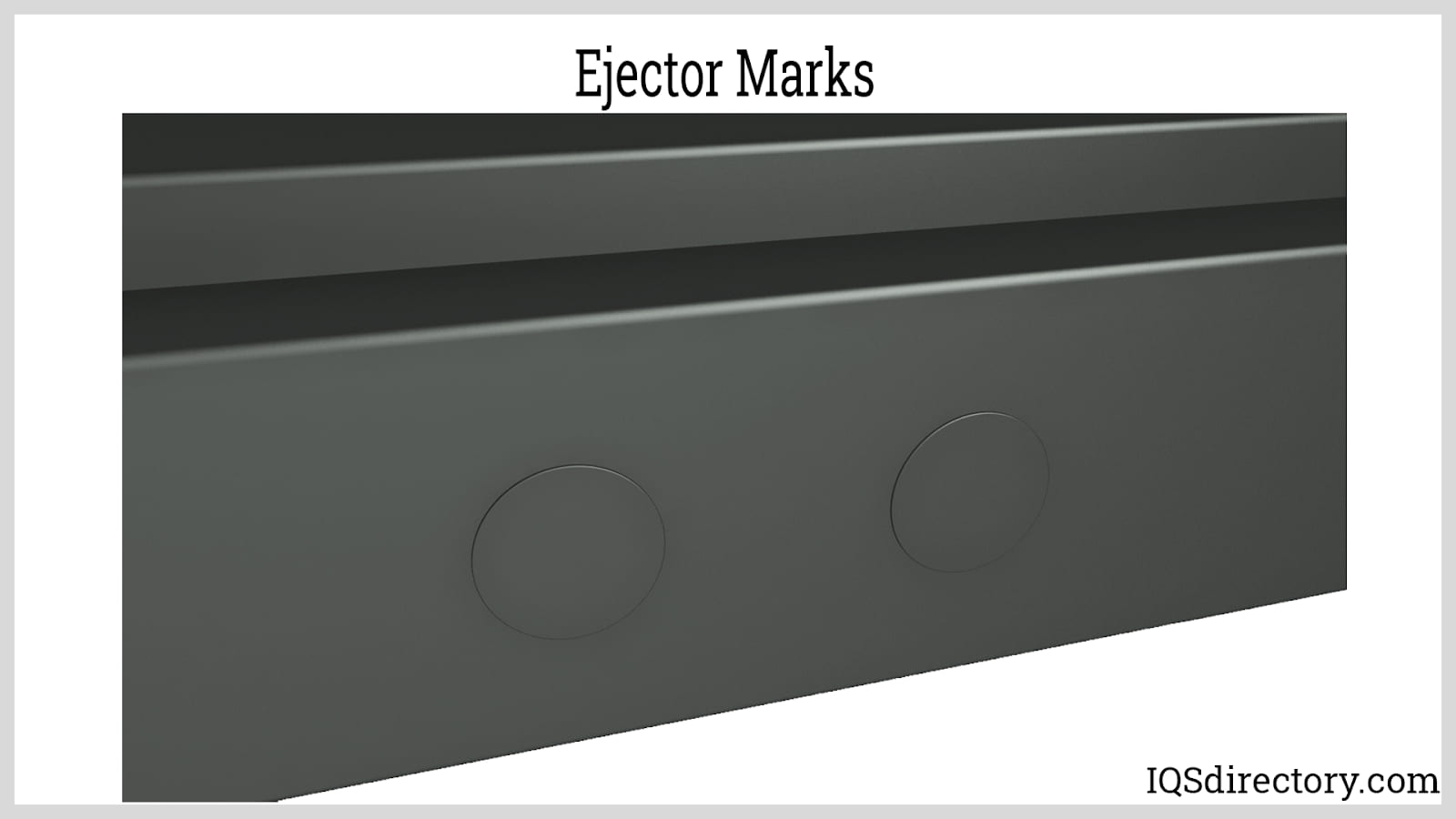
Once the part has cooled and solidified, it is ejected from the mold using ejector pins, which can leave visible marks on the surface. Therefore, it is important to strategically position critical features away from these marks during the design process. To reduce the depth and visibility of these ejector pin impressions, pin sleeves can be employed.
Parting Line
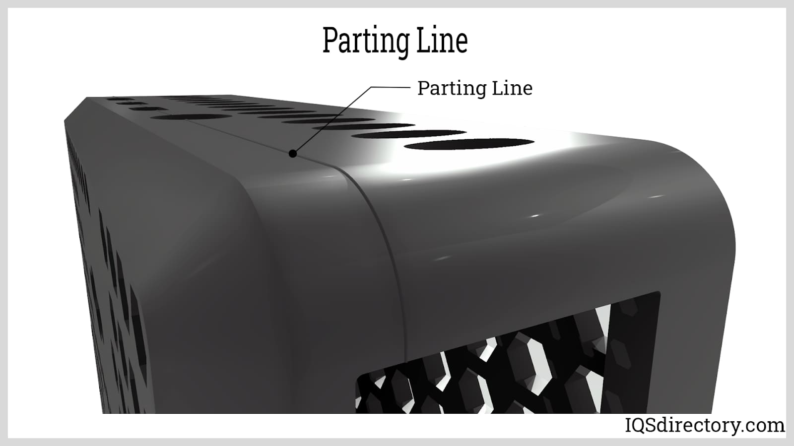
The parting line is the boundary where the two halves of the mold come together, and it leaves a visible seam on the surface of the part. This line can be either straight or curved, depending on the mold design. Since the feedstock flows more easily around the parting line due to air venting, all molded parts will have this seam. While a parting line is unavoidable, its placement should be considered carefully to ensure it does not impact the part’s functionality, appearance, or dimensional accuracy. It is advisable to position the parting line along the edges and to avoid placing critical features directly on it.
Mold Gating
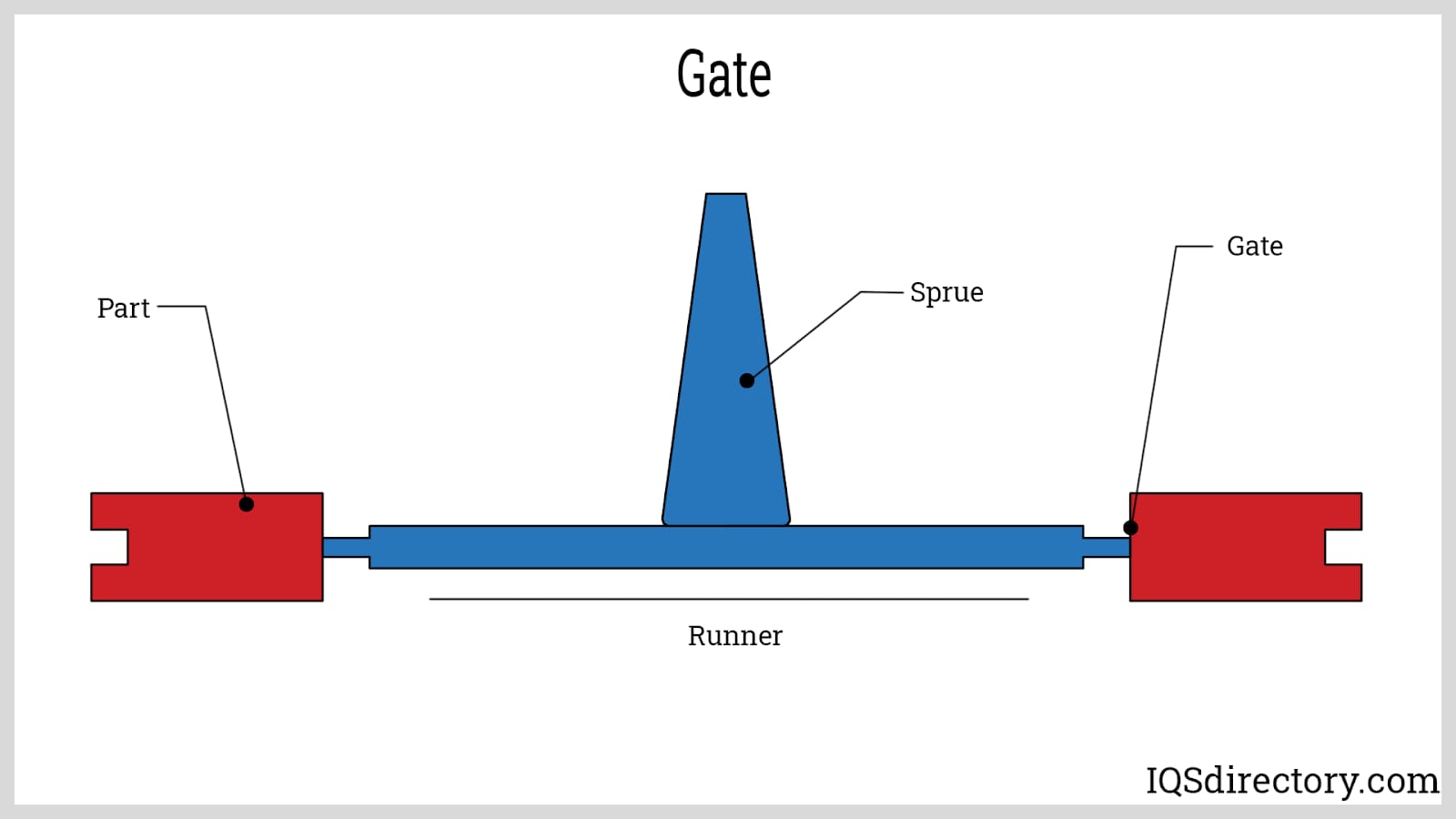
A mold gate serves as the entry point for molten feedstock into the mold cavity. It is strategically positioned at the thickest part of the metal component to ensure that the feedstock fills the larger sections first. Since the gate creates a mark on the final part, it's important to evaluate how this mark might affect the part's performance and appearance.
Part Thickness
Maintaining consistent thickness throughout the part is crucial to prevent issues such as sink marks, warping, and uneven shrinkage during the sintering process. Thinner sections of the part will shrink before thicker sections, potentially causing distortion. It’s important to ensure that any changes in thickness are gradual to avoid these problems.
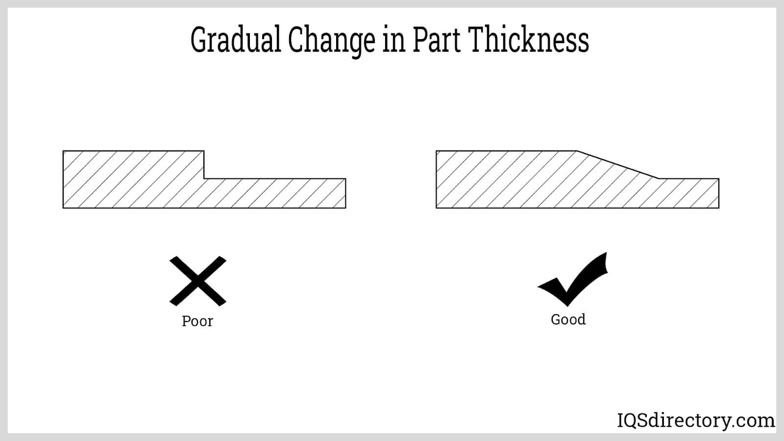
Metal injection molding is effective for creating parts with wall thicknesses between 0.1 mm and 10 mm. Opting for thinner sections can help shorten both the sintering and molding cycle durations.
Corners and Holes
It is advisable to avoid small holes, especially those near corners and edges of the part, as these areas can be prone to void formation. Sharp corners can impede the flow of molten feedstock, so incorporating rounded corners into the part design is preferred for improved fill and overall part integrity.
Producing Undercuts
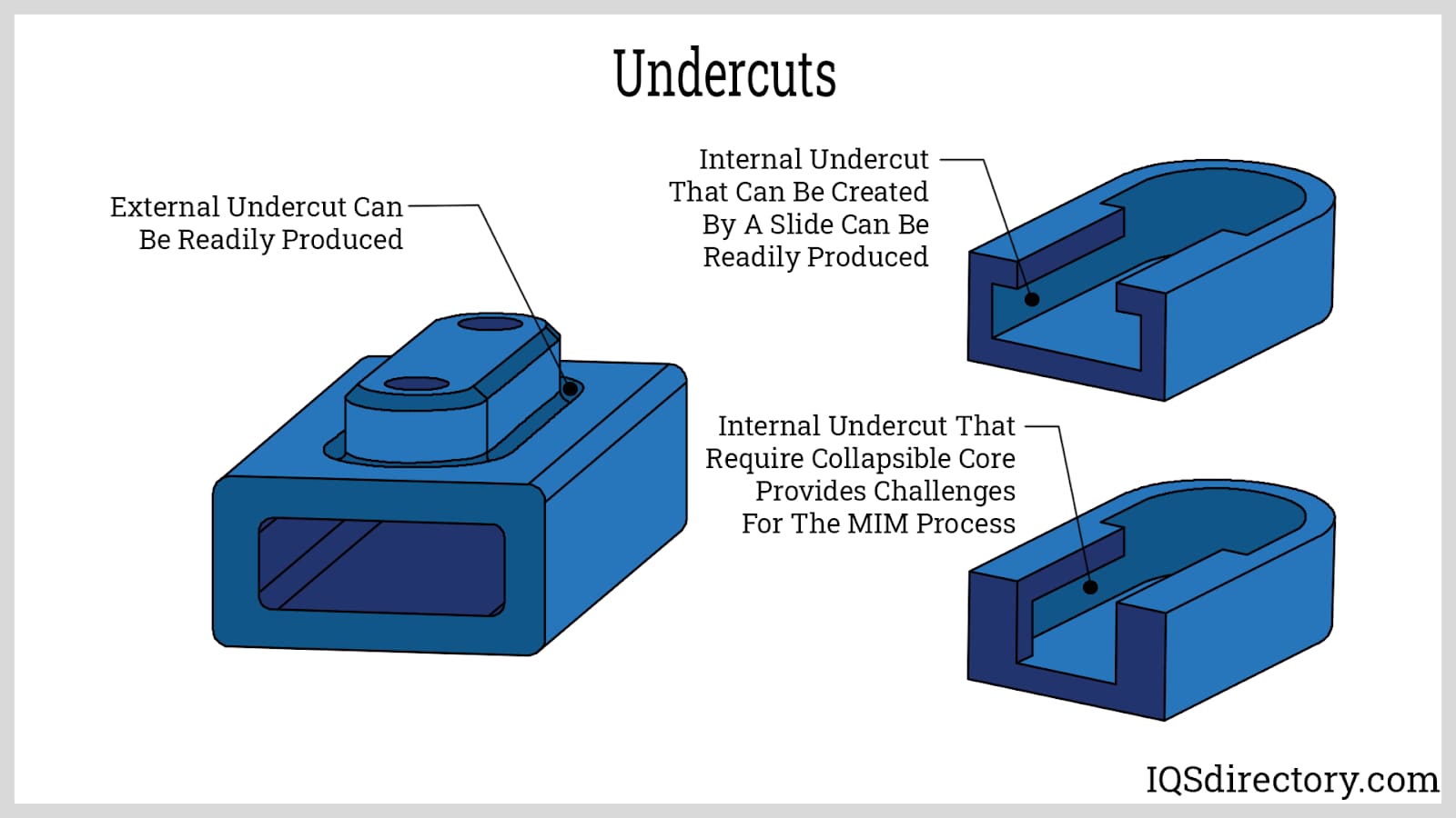
Metal Injection Molding (MIM) allows for the creation of undercuts without additional machining. To achieve this, a cam mechanism is used during molding. This cam is inserted into the mold prior to closure and then retracted from the green part before ejection. It is important to avoid placing undercuts on internal bores, as this can complicate the molding process.
Sintering Process
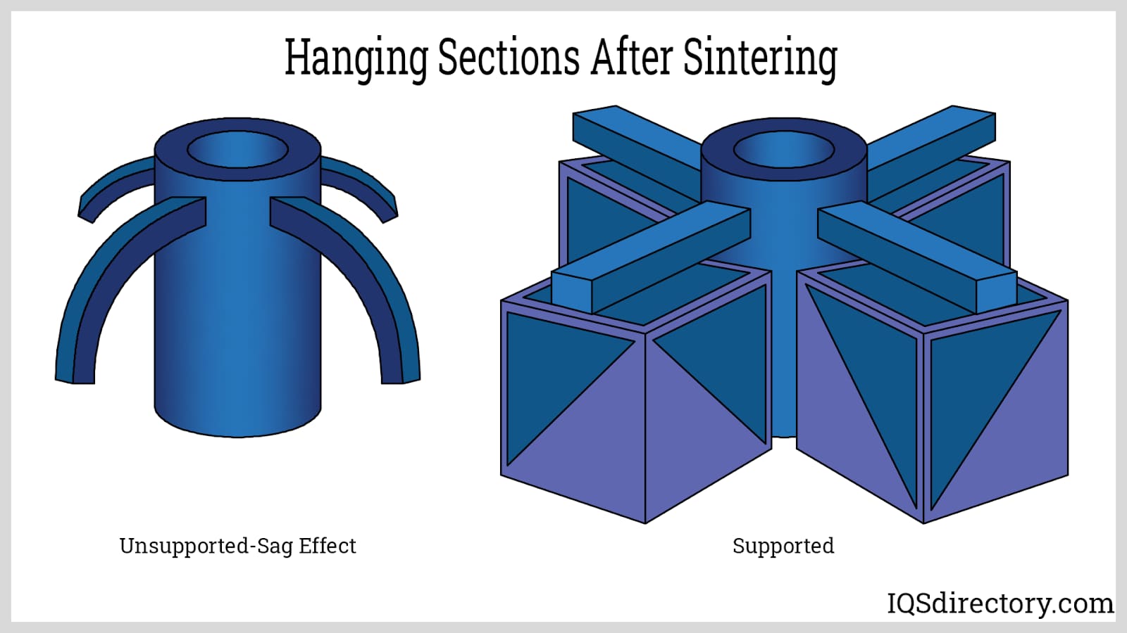
Flat components can be easily positioned in conventional flat support trays during the sintering process. However, any hanging sections of the part might droop or collapse under gravity. Therefore, a specialized fixture is required to provide support for these sections.
Conclusion
- Metal Injection Molding or metal injection molding (MIM) is the process of manufacturing metal parts through injection molding technology.
- The stages of a MIM process are feedstock preparation, injection molding, debinding, and sintering.
- The binder is a thermoplastic additive added to the metal powder to make it suitable for injection molding. It is an intermediate ingredient that is removed after shaping the metal (during debinding).
- Metal injection molding takes place in a standard injection molding machine consisting of a clamping unit, an injection unit, and a mold tool.
- The debinding methods employed in MIM are thermal debinding, catalytic debinding, solvent debinding, and supercritical fluid debinding.
- A hot isostatic pressing (HIP) step may be employed to increase the part's density further and eliminate defects such as voids, cracks, and pores.
- MIM can support the high-volume manufacturing of geometrically complex parts with intricate details. It offers design flexibility, produces parts with superior mechanical properties, and can be performed on a wide range of materials. It may be less expensive compared to investment casting and machining.
- However, MIM may require a high capital investment and processing costs and is not suitable for small production runs. MIM can be a complicated metal fabrication process.
- Ejector marks, parting line, gating, part thickness, corners, holes, and undercuts must be considered during the design phase. Fixtures must support hanging sections of the parts to prevent sagging.