AC DC Power Supply
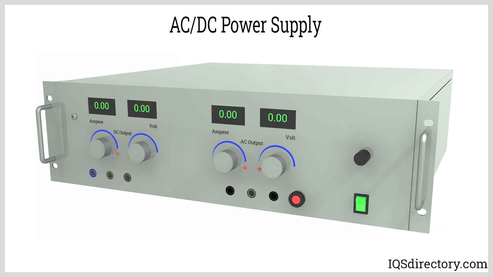
Power supplies are electrical circuits and devices that are designed to convert mains power or electricity from any electric source to specific values of voltage and current for the target device...
Please fill out the following form to submit a Request for Quote to any of the following companies listed on
This article contains everything you need to know about EMI Filters and their use.
You will learn:
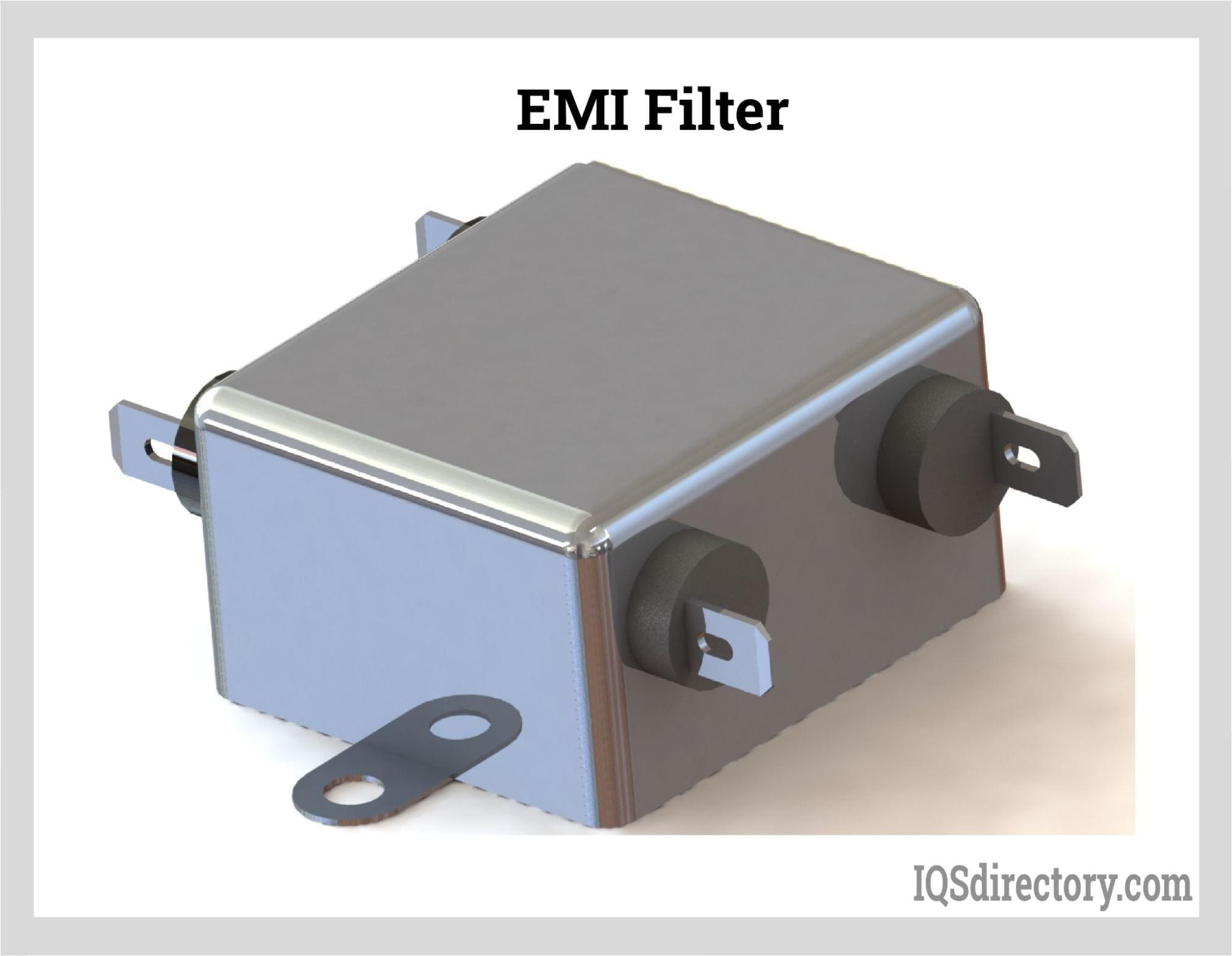
An electromagnetic interference (EMI) filter is a crucial electrical component or circuit engineered to filter out undesirable frequencies from power lines or signals that might disrupt a system's operation. It receives AC or main power, processes it to filter out the undesired noise, and then delivers a clean output signal to optimize device performance. Commonly referred to as a choke, an EMI filter minimizes high-frequency electromagnetic interference in power and signal lines. These filters are categorized as low pass, high pass, bandpass, or band reject and usually incorporate passive components such as capacitors and inductors, arranged either in LC circuits or more intricate setups.
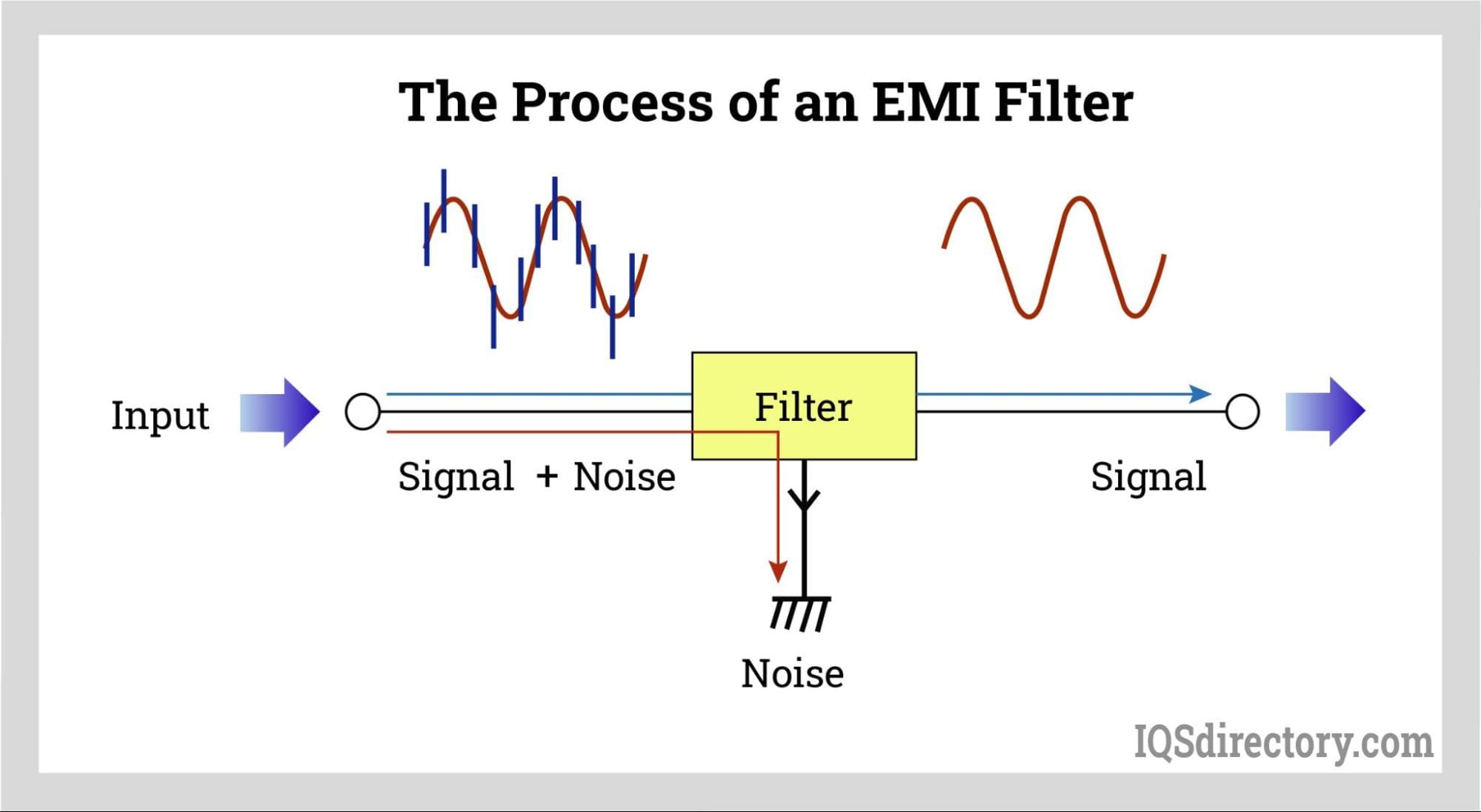
EMI filters leverage the properties of capacitive and inductive materials to eliminate high-frequency noise from signals. They function by either absorbing or reflecting the noise mixed with the genuine signal, producing a cleaner signal output.
Insufficient protection against EMI can significantly hinder the performance of electrical devices, causing undesired currents and voltages to appear in the circuits. EMI can be either conducted, traveling along a physical path from source to recipient, or radiated.
Radiated EMI, in contrast, doesn’t require physical pathways and spreads through the air. This interference occurs when a device emits electromagnetic energy as an electric field, which can lead to damage by overwhelming the circuitry of other equipment. Such emissions might cover vast distances, disrupting the operation of devices.
Beyond external disturbances, internal EMI can also induce interference within a system. This internal interference might arise when sensitive components are placed close to high-voltage or high-current power management circuits, resulting in electromagnetic interference between various circuits.
EMI filters, also known as electromagnetic interference filters or RFI (radio frequency interference) filters, are critical components utilized in a wide range of electronic devices and electrical systems to suppress unwanted electrical noise. These filters come in a diverse array of sizes, designs, shapes, and configurations, each engineered to shield sensitive equipment, such as medical devices, industrial controls, and consumer electronics, from harmful electromagnetic disturbances and power line noise. EMI suppression enhances system safety, reliability, and performance. Broadly, EMI filters are classified into two main types: active and passive EMI filters, each catering to different applications and user requirements.
Active EMI Filters: Active EMI filters leverage an internal power supply to generate a counteracting current that cancels out interference or disturbances. These advanced filters monitor the input voltage and emit a current flow in the reverse direction to neutralize unwanted electrical noise. Employing active electronic components such as operational amplifiers and feedback circuits, active EMI filters are highly effective at reducing both common mode and differential mode noise, especially at low and high frequencies.
Passive EMI Filters: In contrast, passive EMI filters absorb and dissipate unwanted energy rather than generating opposing currents. Constructed from passive filter components such as capacitors, resistors, transformers, and inductors, passive filters are designed to create electrical resonance at specific frequencies or frequency bands, efficiently attenuating conducted and radiated electromagnetic interference. These filters suppress harmonic currents and minimize voltage distortion, making them ideal for power electronics, motor drives, photovoltaic (solar) systems, and industrial automation.
The widespread adoption of EMI filters is attributed to their proven effectiveness in protecting sensitive electronic circuits from both conducted and radiated EMI. Quality EMI/RFI filters eliminate disruptive interference on signal and power lines, permitting only desired signals to pass through, which is essential for compliance with international EMC (electromagnetic compatibility) standards and regulations.
Single-phase EMI filters are specifically engineered for use in single-phase AC power systems and are commonly installed in household appliances, office equipment, and laboratory instruments. These filters provide both common mode and differential mode noise suppression, acting as general-purpose devices to reduce conducted noise and interferences traveling on the power line. By restricting the amplitude of interfering voltages present on AC power lines, single-phase EMI filters play a crucial role in EMC compliance and in ensuring the reliable operation of electronic equipment. For design engineers, choosing the right filter involves considering insertion loss, rated voltage, rated current, and filter bandwidth.
Three-phase EMI filters are designed for robust noise suppression in industrial, commercial, and medical equipment that uses three-phase power. Engineered to manage higher interference levels, these filters employ a three-phase configuration suitable for applications operating within a frequency range of 47 Hz to 400 Hz. Typical uses include frequency converters, motor drives, CNC machinery, and automation systems where high-current applications are common. The two primary three-phase filter topologies are Wye (star) and Delta:
When selecting a three-phase EMI filter, engineers should consider factors such as leakage current, filter attenuation, physical footprint, rated voltage, and safety certifications (UL, CE, RoHS) to optimize performance for their intended application.
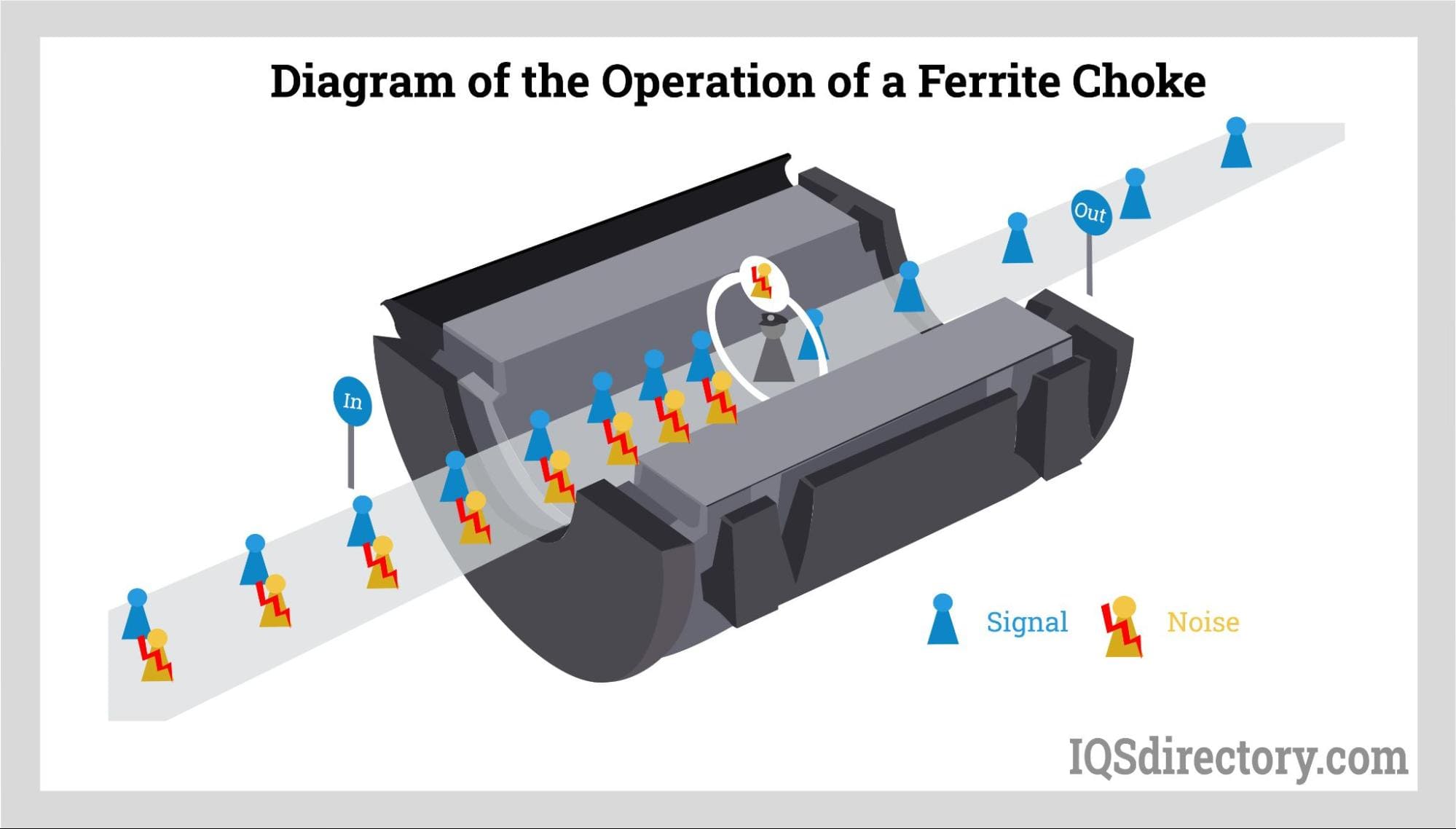
Among the most versatile and cost-effective passive EMI suppression solutions are ferrite chokes—also known as ferrite bead filters, ferrite collars, ferrite clamps, and ferrite rings. Acting as low-pass filters, ferrite chokes attenuate high-frequency noise and are commonly used to reduce EMI in data cables (HDMI, USB, Ethernet), audio/video wires, power supply lines, and medical cables to support compliance with FCC and CISPR standards.
The core of a ferrite choke is composed of a magnetic ferrite material, which provides high inductive resistance to high-frequency signals while allowing low-frequency currents to pass. The nonlinear resistance of ferrite beads depends on current, voltage, and temperature. The proper placement of ferrite chokes—typically 5 cm from the device's power or signal connector—significantly enhances their EMI attenuation efficiency.
Choosing the optimal ferrite choke type and size hinges on factors such as cable diameter, frequency range of unwanted interference, rated current, and the application's environmental conditions. Ferrite cores with different impedance profiles are available for broadband and narrowband noise filtering, addressing both differential mode and common mode EMI issues.
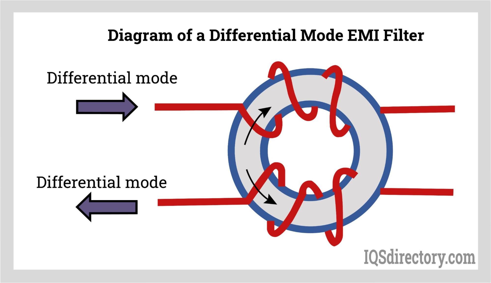
Differential mode passive EMI filters are designed to attenuate high-frequency AC currents (noise) that flow in opposite directions through the conductors in a circuit. Often deployed as LC filters or common mode chokes with added capacitors, these filters can be customized by varying coil winding, material selection, and magnetic core composition to meet diverse interference mitigation requirements.
These filters work by using magnetic cores with windings connected in such a way that differential signals are impeded, while common mode currents pass largely unaffected. Differential mode EMI suppression is vital in power supplies, DC-DC converters, photovoltaic inverters, wind turbine electronics, automotive powertrains, and telecommunications base stations. Key criteria for filter selection include impedance, current rating, insertion loss, resonance frequency, and overall filter reliability for mission-critical electronics.
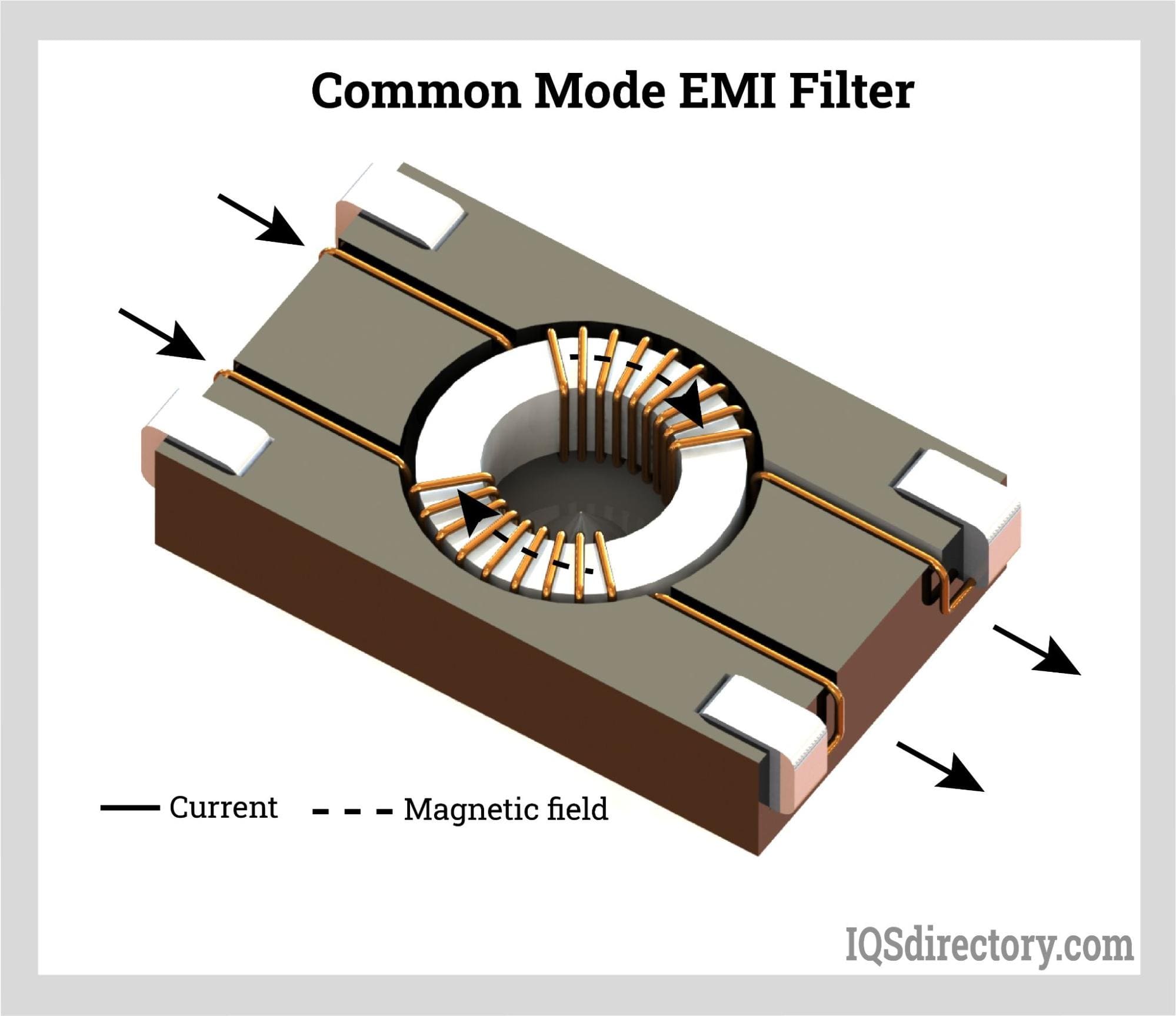
Common mode passive EMI filters focus on blocking high-frequency noise currents that are present in the same direction on both power lines. Such electromagnetic disturbances may be radiated or conducted, stemming from switching power supplies, inverters, unshielded electronics, and motors—common sources of radio frequency (RF) noise and conducted emissions. The principle of operation involves producing opposing magnetic fields in the core, allowing only desired low-frequency signals to pass and offering effective RF filtering in both industrial and consumer electronics.
Common mode EMI filters are categorized by the frequency band addressed: RF EMI filters (for frequencies above 30 kHz) and AF EMI filters (targeting audio frequency noise up to 30 kHz). Applications for RF EMI filters include digital communication devices (USB, HDMI, LVDS, CAN bus, Ethernet), while AF EMI filters are found in switch-mode power supplies, rectifiers, electrical ballasts, variable frequency drives, and power inverters.
The materials chosen for filter cores—solid iron for AF and powdered ferromagnetic alloys for RF—ensure optimal noise attenuation and compliance with EMI and EMC guidelines. Selecting the appropriate core and filter structure is critical to minimize leakage current and optimize suppression of both radiated and conducted EMI, thus achieving certification and protecting sensitive equipment.
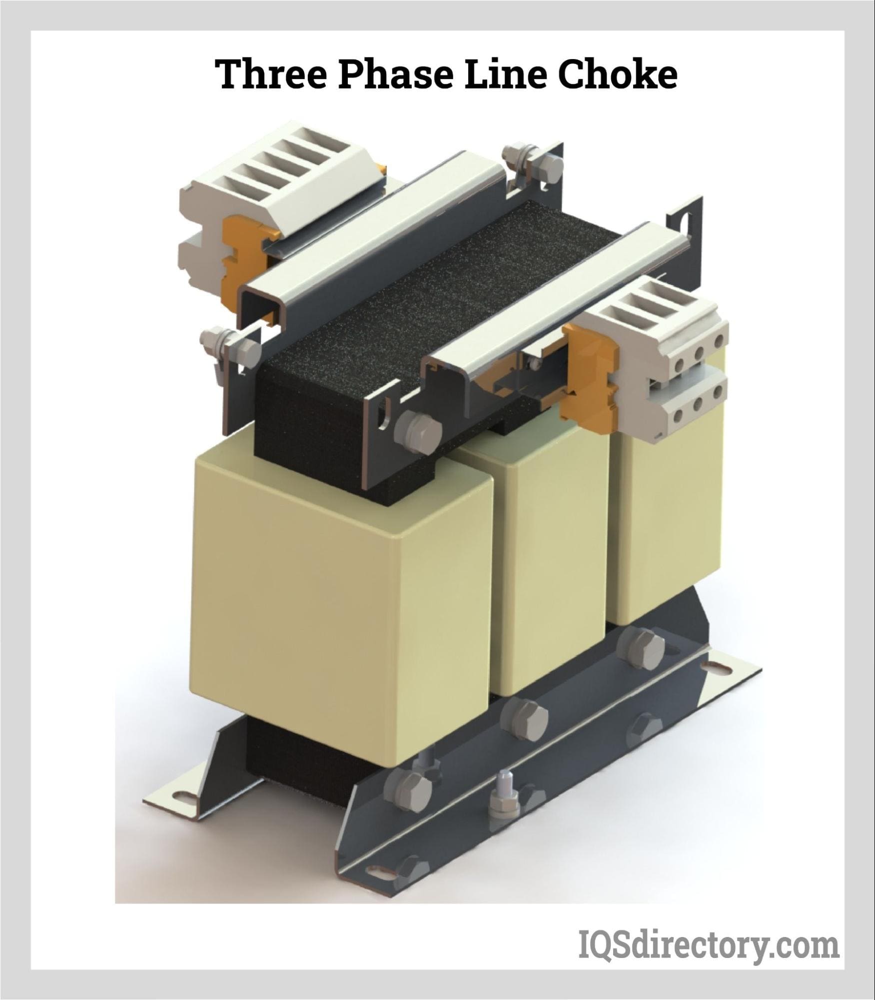
Line chokes, also called AC line reactors, play an essential role in mitigating harmonic distortion and spikes generated by switching devices or variable frequency drives (VFDs). Installed in series with VFD inputs or outputs, line chokes enhance EMC performance by limiting inrush currents, reducing high-frequency transients, and protecting both the drive and connected motor. These components are used to suppress harmonics, manage sinusoidal currents, and extend equipment longevity by providing vital surge and lightning protection.
For installations where multiple drives are connected or where long cable runs (over 100 feet) are required, output-side load reactors (output chokes) prevent voltage reflections and standing waves that can damage motor insulation. Three-phase line chokes are indispensable in mitigating harmonics generated during AC to DC rectification, protecting sensitive electronics and reducing energy loss due to excessive heat.
Engineers must size line chokes appropriately for voltage, current, and inductance to ensure compatibility with the AC power lines and system load requirements. Line chokes are central to power quality improvement, motor control systems, and EMI reduction strategies for industrial automation and building management systems.
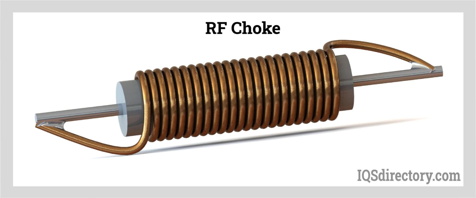
RF chokes (radio frequency chokes) are specially designed fixed inductors that block or attenuate high-frequency alternating currents (RF signals) while allowing desired DC or low-frequency AC signals to pass. With broad impedance across the RF spectrum, RF chokes can filter out electromagnetic interference in wireless equipment, radio transmitters, communication receivers, and antenna systems, as well as power supplies for sensitive audio devices.
These chokes consist of coils wound around magnetic cores or ferrite beads, which are engineered with minimal self-capacitance for maximum noise attenuation. In modern electronic circuit design, RF chokes help prevent radio frequency interference from being conducted along power or signal lines, ensuring signal integrity and compliance with EMI regulatory standards.
Power chokes are essential for noise filtering and ripple reduction, ensuring steady DC voltage at the output of power conversion circuits. Positioned between the mains and the inverter or DC bus, power chokes smooth current fluctuations, filter line noise, and help maintain equipment safety and EMC compliance. Featuring high inductance and low DC resistance, power chokes are extensively used in switch-mode power supplies, UPS systems, and high-efficiency power conversion modules. Proper selection based on current, temperature rise, and voltage withstand helps prevent electromagnetic noise and increases overall system reliability.
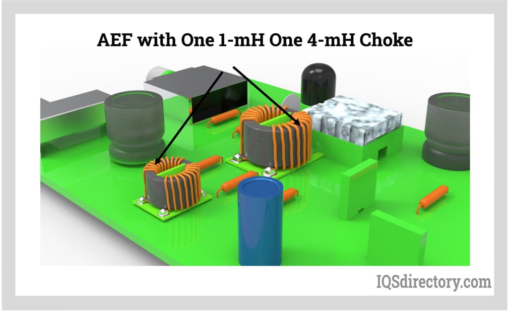
Active EMI filters, or AEFs, utilize advanced circuit topologies—often incorporating operational amplifiers, precision capacitors, and feedback loops—to target both common mode and differential mode noise in high-density power electronics. These filters represent an evolution in EMI mitigation, offering greater efficiency in a compact form factor. The primary advantages of AEFs include strong EMI suppression (15 dB to 30 dB common mode rejection within 100 kHz to 3 MHz), lower design complexity, and cost-effective integration in modern high-frequency devices, like EV chargers and renewable energy inverters.
By continuously sensing and injecting counteracting currents to suppress unwanted signals, AEFs provide a low-impedance path for EMI, complementing or replacing bulky passive EMI filters. Next-generation systems benefit from smaller size, lower weight, and optimized thermal performance, aligning with increasing industry demands for miniaturization and higher power density. When integrating AEFs, focus on system compatibility, thermal management, certification requirements, and the impact on total harmonic distortion (THD) for optimal EMI compliance.
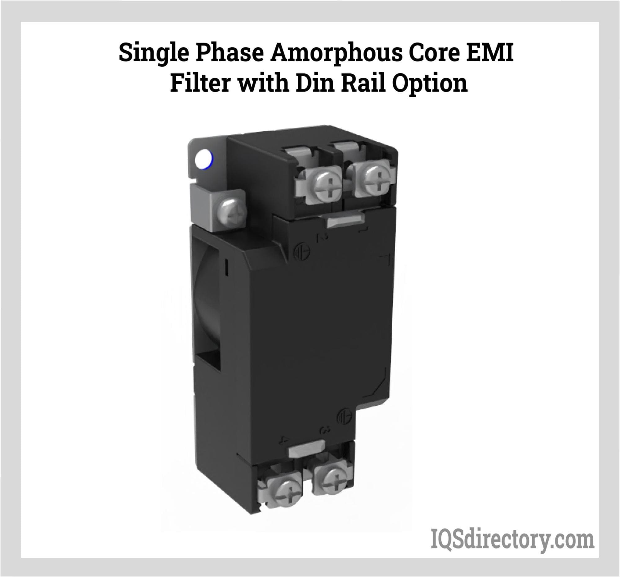
Amorphous core EMI filters use amorphous metal alloys as their magnetic core material, providing exceptionally high permeability and minimal core loss even at elevated frequencies. This enables superior noise suppression for both conducted and radiated emissions while ensuring a lightweight, compact design. The unique, non-crystalline structure of amorphous metals (typically composed of iron, silicon, and boron) enhances their magnetic efficiency, making these filters especially effective for high-frequency and high-voltage applications.
Applications of amorphous core EMI filters span a wide range, from modern power supplies, electric vehicle charging stations, industrial drives, and telecommunications equipment to precision audio and A/V installations. Both common mode and differential mode amorphous EMI filters are available, with designs tailored to mitigate specific types of noise in demanding environments. Selection criteria include core material type, inductance, maximum current, and compliance with industry EMC standards such as CISPR, FCC, and EN.
How to Choose the Right EMI Filter for Your Application
When selecting an EMI filter for your specific application, consider the following key factors: source and type of interference (conducted or radiated EMI), frequency range to be suppressed, type of load, installation environment, system voltage and current, leakage current requirements, and applicable EMC regulations. Different industries—from industrial automation and renewable energy to medical devices and automotive electronics—face unique EMI challenges that require tailored filter solutions. Consulting with an experienced EMI filter manufacturer or supplier is recommended to ensure compatibility, safety, and regulatory compliance.
Additionally, thorough EMI compliance testing (using standards like CISPR 22/32, FCC Part 15, or EN 55011/32) is crucial for CE marking, FCC approval, or other certifications required for electronic products entering the global market. Proper EMI filter integration not only guarantees device safety and functionality but also helps avoid costly redesigns and certification delays.
Electromagnetic interference (EMI) occurs when unwanted electromagnetic signals, disturbances, or electrical currents disrupt the intended operation and signal integrity of electronic devices. This interference—commonly referred to as noise, electromagnetic noise, or RF interference (radio frequency interference)—can be either radiated or conducted and may originate from both external and internal sources. EMI poses a significant challenge in electronics design and operation, as it can cause reliability issues, temporary malfunctions, permanent system failure, or degrade the performance of communication and power systems.
Both conducted and radiated forms of EMI can severely impact electronic components and systems. Effects include reduced device functionality, data loss, erratic behavior, audio or video quality degradation, and even the complete shutdown of critical systems. This underscores the essential role of robust EMI shielding, EMC (electromagnetic compatibility) design, and high-performance EMI filters in protecting sensitive electronics and maintaining system reliability in modern high-frequency environments.
Natural sources of EMI, also called environmental electromagnetic interference, are unpredictable and often sudden, potentially producing significant and lasting damage to unshielded or unprotected devices. Phenomena such as lightning strikes and solar storms can create strong electromagnetic fields capable of inducing surges and signal disturbances in power distribution networks, communication infrastructure, and navigation equipment. Critical technologies—including military communication systems, air traffic control networks, and civilian transportation technologies—are particularly susceptible given society’s growing dependence on electronic devices for safety and information.
Common types of natural EMI include:
For example, alignment of sunlight directly behind a satellite can introduce powerful electromagnetic noise that disrupts satellite communications, GPS navigation, and television signals. Meanwhile, snowstorms and adverse weather conditions can create static charges, interfere with wireless radio signals, and degrade performance in consumer devices such as laptops and cellular networks.
Residential EMI, also called domestic electromagnetic interference, primarily stems from the increased presence of wireless signals and a variety of consumer electronics and home appliances. While typically less destructive than industrial EMI, it can still cause frustrating disruptions, including dropped Wi-Fi connections, audio dropouts in Bluetooth speakers, or erratic device behavior. With the proliferation of smart home technology and the Internet of Things (IoT), the frequency and density of electromagnetic disturbances in homes has dramatically increased.
As society’s reliance on interconnected electronic equipment rises, so does the total volume of electromagnetic emissions in residential settings. Everyday devices such as cell phones, tablets, and smart thermostats operate in close proximity, creating opportunities for interference. The ongoing trend toward high-frequency, high-speed device architecture exposes these electronics to a wider electromagnetic spectrum, sometimes overwhelming basic filtering and shielding methods.
Modern electronic appliances, striving for improved power efficiency and compact design, often generate larger amounts of electromagnetic noise and are more susceptible to radio frequency interference (RFI) and harmonic distortion. This evolution has pushed EMI filter manufacturers and electronics engineers to continuously develop advanced solutions—such as multi-layer PCB shielding, ferrite beads, and noise suppression components—to ensure optimal protection and compliance with EMC regulations.
Common Human Residential EMI Sources:
The increasing use of power electronics and wireless communication devices, often operating on overlapping frequency bands (such as Wi-Fi and Zigbee), can also generate electromagnetic compatibility challenges that must be assessed during home electronics selection and installation.
Industrial EMI, or electromagnetic interference arising from commercial and manufacturing facilities, is a major concern due to the high power levels, large-scale equipment, and densely interconnected systems present in these environments. Industrial sources regularly create strong electromagnetic fields, radio frequency emissions, and sudden voltage transients that can cripple sensitive technologies across sectors such as healthcare, defense, communications, and energy transmission. Large disturbances may disrupt hospitals, interfere with medical imaging equipment, destabilize industrial process control systems, or even affect public transportation and power grids.
Examples of high-frequency and high-power industrial EMI sources include transmitters, transformers, inverters, variable frequency drives, switching power supplies, and digital controllers.
Categories of EMI in Human Industry:
To minimize industrial EMI, best practices such as proper cable management, electrical grounding, regular EMI testing, and implementing advanced shielding and filter design are crucial for maintaining regulatory compliance (like FCC, CE, or CISPR standards) and functional safety.
Beyond external EMI sources, internal electromagnetic interference within a device or electronic system is also a pressing issue for product developers and circuit designers. Dense component layouts, high-speed microprocessors, and compact printed circuit boards (PCBs) can cause crosstalk, ground loops, and mutual inductance, leading to signal degradation or data errors. For instance, in smartphones or embedded systems, a digital processing module may emit EMI that impairs the operation of sensitive analog circuits or wireless transceivers.
Modern circuits frequently use switch mode power supplies (SMPS) for higher efficiency, but the rapid switching of semiconductors (e.g., field-effect transistors, or FETs) generates transient noise and broadband EMI. Effective suppression often relies on differential mode (DM) and common mode (CM) EMI filters, PCB layout optimization, careful shielding placement, and the selection of low-noise electronic components.
When developing or purchasing electronic devices or systems, evaluating EMI susceptibility through pre-compliance EMC testing and ensuring the integration of proven noise reduction strategies is vital. As end-users increasingly search for “low EMI electronics,” “EMC certified devices,” or “best EMI filtering solutions for sensitive equipment,” providing transparency about EMI mitigation in product documentation and marketing content can directly impact user trust and purchasing decisions.
Before choosing an EMI filter, it's crucial to assess the specific requirements of the electrical system. Different EMI filters have varying limits, frequency ranges, and suppression methods. Review filter data sheets that include insertion loss data and tables, which indicate the loss in signal power between the filter’s input and output and the attenuation provided at specific frequencies, measured in decibels.
Conducted noise, whether common or differential, depends on its location and propagation method. During data collection, charts for both common and differential noise are available. Analyzing this data helps determine the failure margin for each frequency, assessing whether the filter provides enough attenuation to bring noise levels below acceptable limits. Similar tests should be conducted for radiated noise as well.
After gathering data, it's important to review the system's requirements and specifications, including voltage, current, operating and ambient temperatures, dielectric withstand voltage, leakage current, and feed system type. Evaluating these specifications ensures that the filter can handle the system's needs without compromising performance or reliability.
Single-phase EMI filters are typically rated for 250 VAC and are compatible with any AC voltage below this threshold. For three-phase systems, filters are generally rated for 480 VAC. Some single-phase filters are available with ratings up to 277 VAC or 300 VAC for higher voltage applications.
Current ratings for EMI filters can range from less than 1 amp to over 1000 amps. This rating indicates the maximum continuous current the filter can handle within its specified temperature range. It should match or exceed the maximum input current of the device. While most filters can tolerate higher inrush currents, they may fail if the rated current is exceeded for prolonged periods.
To determine the current rating of a device, examining its safety certificate, such as the UL report, can be useful. The report provides details on the full load nominal input and the recommended filter rating. Additional power supplies and AC loads may require filters with different ratings.
There are two temperature considerations: ambient and operating. Ambient temperature refers to the maximum temperature at which a filter can handle its full rated current, typically between 40°C and 50°C. If the operating temperature exceeds the ambient temperature rating of the filter, the current rating must be derated.
The operating temperature is the range within which the filter can function safely, usually between -25°C and 85°C or 100°C for most filters. Using a filter outside this range can lead to component damage.
Leakage current is the current that flows from the line and neutral to ground when line voltage is applied to the filter. This is caused by the line-to-ground capacitor within the filter. EMI filters with Y capacitors can add additional leakage current. Regulatory standards limit leakage current and must be adhered to strictly for safety.
Power systems differ globally and include configurations beyond single phase, 3 phase delta, and 3 phase wye. EMI filters are designed for these configurations and DC circuits but can be adapted for other systems with minimal adjustments. It is essential to identify and match the input power supply type with the selected filter.
The term "stages" refers to the number of circuit repetitions within a filter. A single-stage filter has one circuit, while dual-stage and multi-stage filters include additional circuits. Increasing the number of stages generally enhances filter performance.
The hipot test evaluates the dielectric strength of the insulation by applying a DC voltage between the line and ground. This test helps identify weak points in insulation or manufacturing defects. The voltage used is the rated value specified by safety standards, though higher requirements may necessitate adjustments to the filter.
EMI filters come in various sizes, performance levels, interconnections, and mounting types. In some cases, custom-designed filters may be required to meet specific application needs.
The type of equipment and its components are critical in selecting an appropriate EMI filter. Whether for AC/DC converters, manufacturing equipment, medical devices, RF modules, or other equipment, the filter must align with the application's nature. Factors such as clock frequencies and switching frequencies influence the emission profile of an EMI filter.
In power systems, cables and wiring can act as antennas for high-frequency noise, particularly when using open-frame power supplies without the shielding found in enclosed types. The design of power supplies often poses significant challenges in eliminating and mitigating radiated and high-frequency conducted emissions. To effectively address high-frequency noise, it is crucial to install an EMI filter, as it helps prevent the coupling of noise back through the radiated mode.
Following these EMI filter installation recommendations can help ensure optimal filter performance:
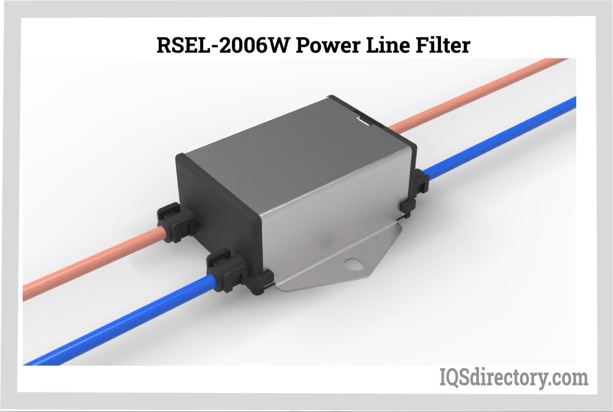
EMI sources often require a multifaceted approach for effective mitigation. During the installation process, it is beneficial to have a variety of EMI filters available. This approach enhances the efficiency of installation and reduces overall filter costs. Manufacturers and suppliers of EMI filters typically offer support services to aid in the selection, design, and installation of filters, as well as to provide guidance on cable routing and noise suppression techniques.
Key components of an EMI filter include capacitors and inductors. Capacitors are used to shunt noise away from the load, while inductors block or reduce noise. Additionally, EMI filters may include circuit protection components such as a fuse, metal oxide varistor, input surge current limiting resistor, and output transient voltage suppressor.
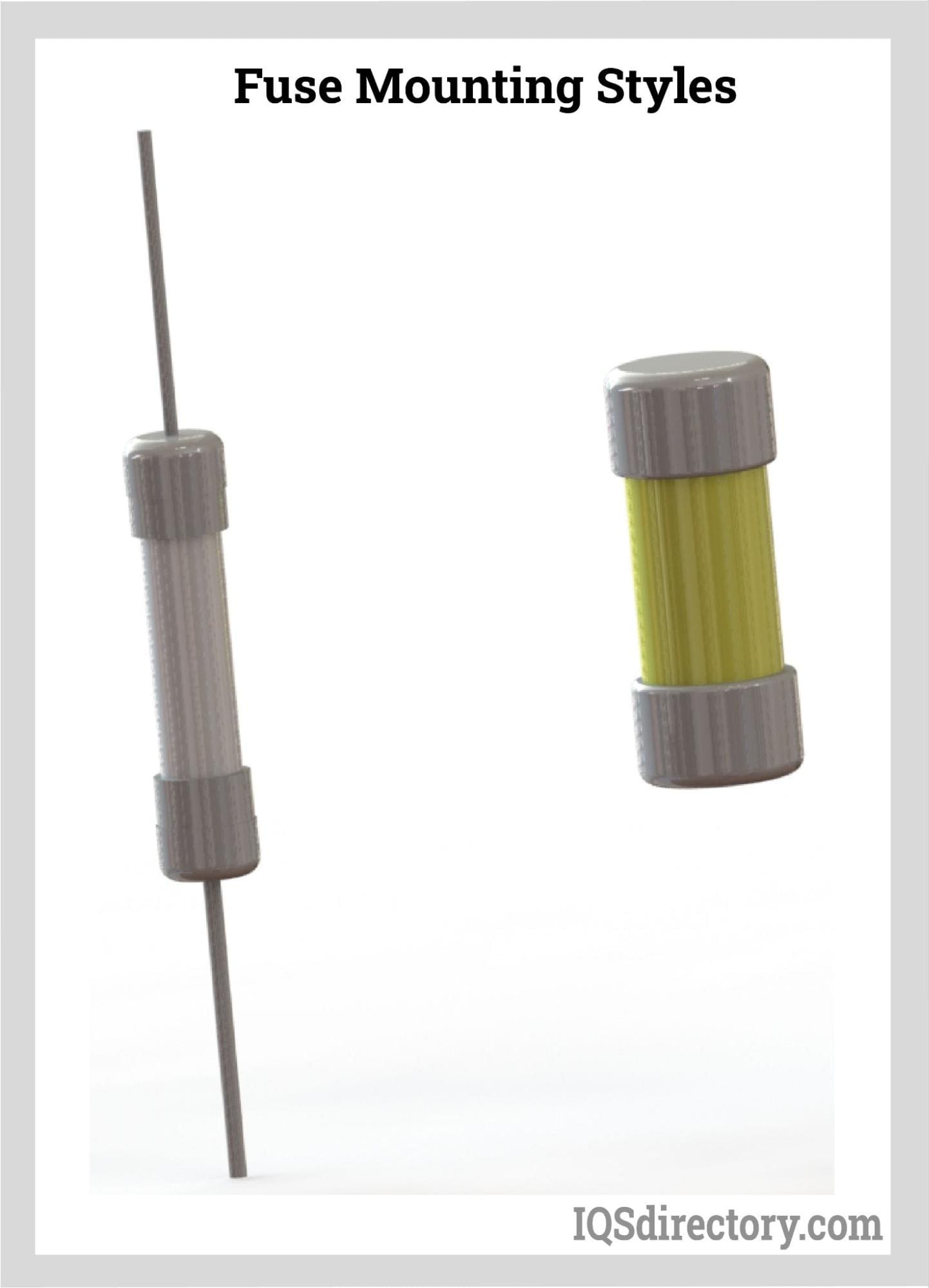
The fuse safeguards the power source and the conductors feeding into the power supply by being placed in series with the input. It is installed on the non-ground input terminal, ensuring that when the fuse opens, no voltage reaches the power supply. Fuses are chosen based on the application's voltage, current, response time, and operating temperature requirements.
The term "varistor" is derived from combining "variable" and "resistor," reflecting its function. A varistor offers over-voltage protection through voltage clamping. It adjusts its resistance automatically as the voltage fluctuates and is designed to absorb transient energy. An input fuse is installed between the varistor and the input power source.
The input surge current limiting resistor helps manage the initial surge of current when AC voltage is introduced to the power supply. This is essential to handle the quick charging of the capacitor that occurs at the moment the input voltage is applied.
Rapid changes in the load can cause the output voltage to fluctuate, resulting in what is known as a transient response. The Transient Voltage Suppressor (TVS) diverts these voltage spikes caused by external sources at the output terminal to safeguard the power supply. While a varistor can serve as a TVS, it is typically not used on the output side due to the lower output voltage in comparison to the input side.
The Differential Mode (DM) choke, combined with the input capacitor, acts as a low pass LC filter to minimize the conducted noise voltage on the input conductors, preventing it from affecting the power source. It is engineered to handle the peak input current effectively.
The Common Mode (CM) choke generates significant resistance to diminish common mode currents traveling through the input conductors. The markings on the CM choke denote the winding direction and orientation. These chokes are selected based on their capability to manage maximum current and ensure adequate power dissipation.
The input capacitor is positioned across the input power lines to divert differential noise and prevent it from reaching the voltage source. These capacitors are constructed to X or Y safety standards, allowing them to be directly connected to the AC input line and endure surge conditions.
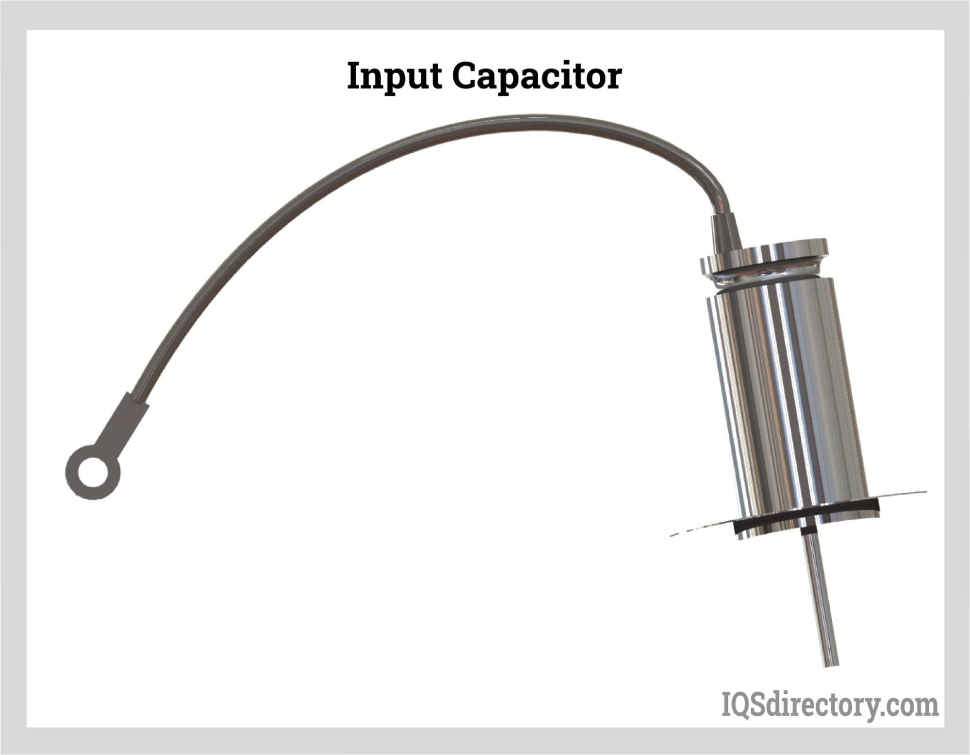
The Y capacitor is positioned between the input and output to mitigate mode voltage noise on the output power supply. It is engineered to fail safely as an open circuit if there is a breakdown between the input and output. This Y safety isolation capacitor is essential due to the waveform generated by the primary switching transistor and the parasitic capacitance between the primary and secondary sides of the isolation transformer.
Filtering components are positioned at the power supply's output terminal and close to the load. These components are chosen based on their effectiveness in minimizing output ripple voltage to a level that is acceptable for the load.
EMI filters are available in various configurations, such as panel mounts with resin or glass encapsulation, surface mounts compatible with PCB layouts, board mounts, d-subminiature connectors, and both single-phase and three-phase power line filters. Essentially, there's an EMI filter suited for virtually every type of electronic, power, signal, and AC/DC application. Their role is crucial in maintaining the high performance and reliability of electronic devices.
EMI filters are primarily used to safeguard electronic devices. They prevent sensitive equipment from being affected by both conducted and radiated noise, which can lead to damage and operational issues. It's essential for all electronic devices to be equipped with an EMI filter to ensure their proper functioning.
Ensuring the safety of electronic equipment involves adhering to a comprehensive set of codes, regulations, and standards. These regulations are particularly relevant in industrial settings where EMI filters are used, as they can generate significant EMI and RFI. Manufacturers of EMI filters are knowledgeable about these requirements and ensure their products meet all necessary standards. Non-compliance with EMI regulations can result in fines, penalties, and even shutdowns in various countries.
While residential electronics might not experience this issue as frequently, high-frequency interference can lead to system shutdowns in industrial and manufacturing environments. EMI filters play a crucial role in maintaining the uninterrupted operation of electronic systems by preventing interference, errors, and malfunctions. Their effectiveness in minimizing issues also helps lower maintenance and repair expenses, positively impacting overall costs.
EMI filters contribute to long-term cost savings, enhance system reliability, and ensure operational continuity, aligning with both national and international standards. As electronic circuit complexity grows, so does the potential for electromagnetic disturbances, increasing the risk of operational errors. EMI filters are essential for mitigating these risks and ensuring stable, error-free performance.
An EMC plan provides a comprehensive overview of a new product, including its testing procedures. It includes detailed information about the product, the specific EMC tests conducted, and the outcomes of those tests. This plan ensures a structured approach to testing and serves as a documented record, helping laboratories deliver precise and coherent data. As sensitive electronics become more prevalent, EMI filters play a key role in managing electrical input currents, which can be monitored and used to safeguard the tested items.

Power supplies are electrical circuits and devices that are designed to convert mains power or electricity from any electric source to specific values of voltage and current for the target device...
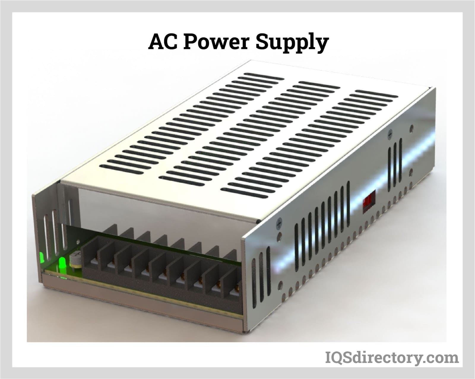
An AC power supply is a type of power supply used to supply alternating current (AC) power to a load. The power input may be in an AC or DC form. The power supplied from wall outlets (mains supply) and...
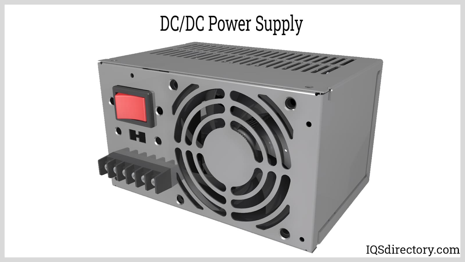
A DC DC power supply (also known as DC DC Converter) is a kind of DC power supply that uses DC voltage as input instead of AC/DC power supplies that rely on AC mains supply voltage as an input...
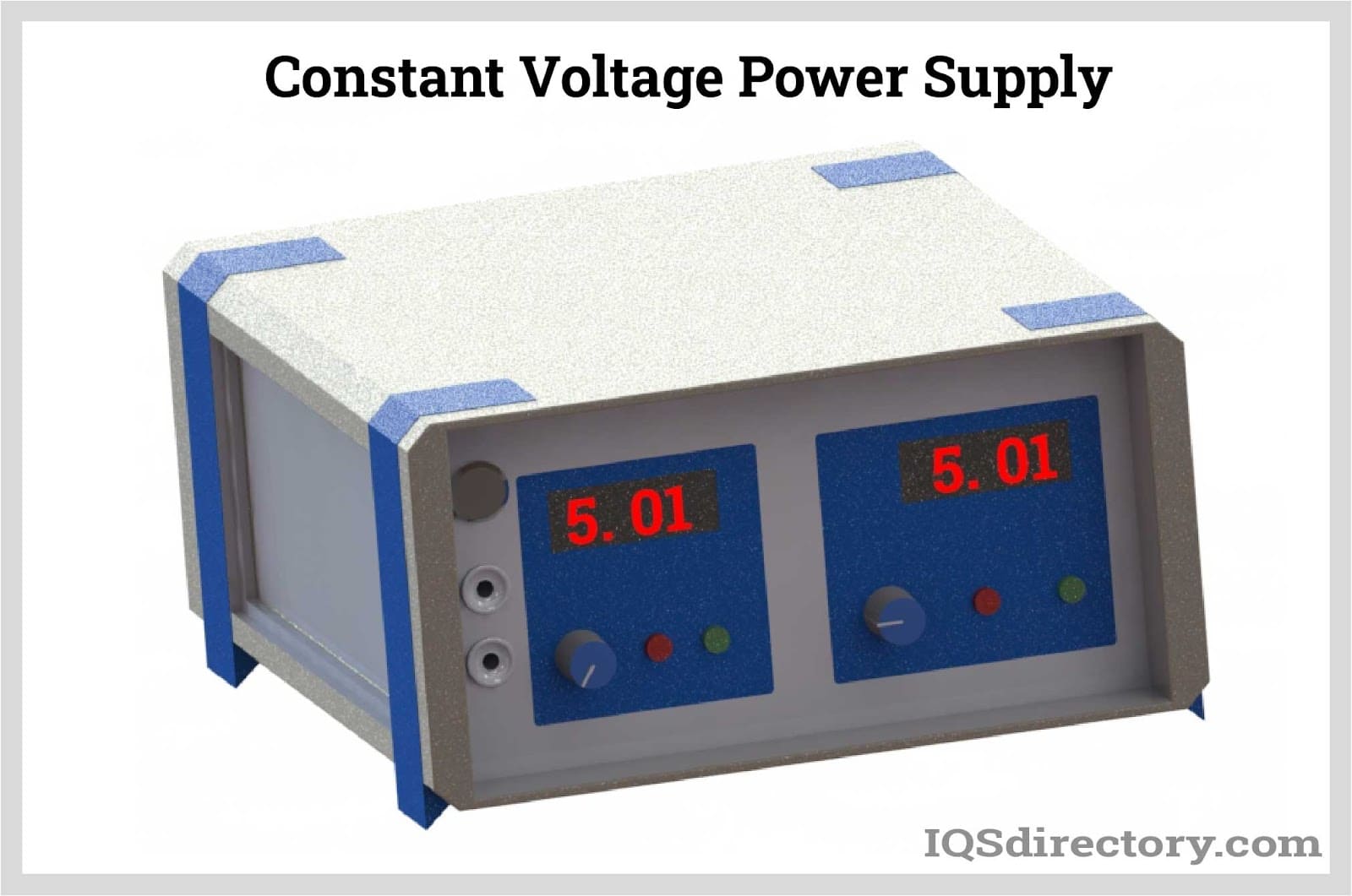
A DC power supply is a type of power supply that gives direct current (DC) voltage to power a device. Because DC power supply is commonly used on an engineer‘s or technician‘s bench for a ton of power tests...
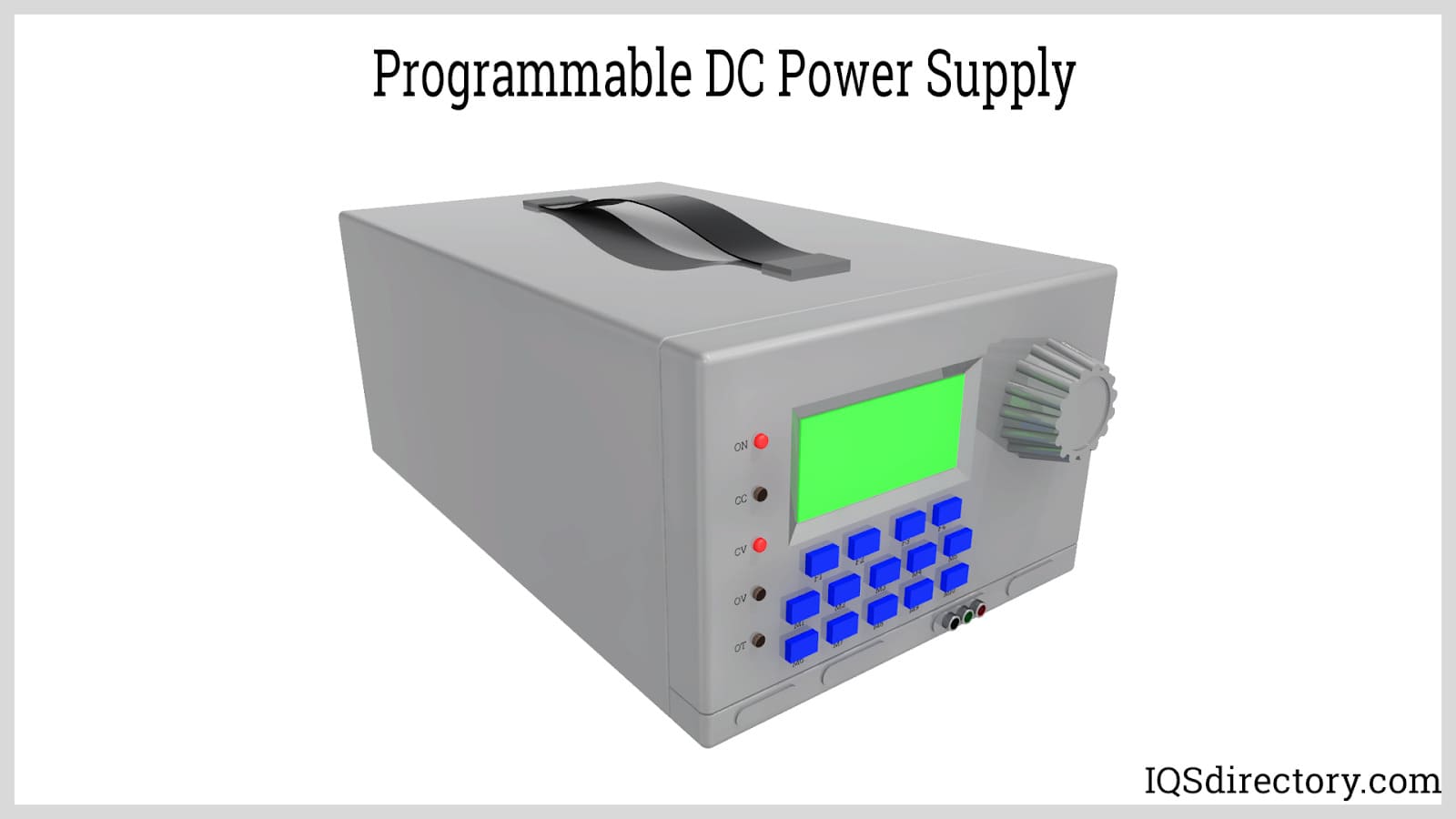
A programmable power supply is a method for controlling output voltage using an analog or digitally controlled signal using a keypad or rotary switch from the front panel of the power supply...
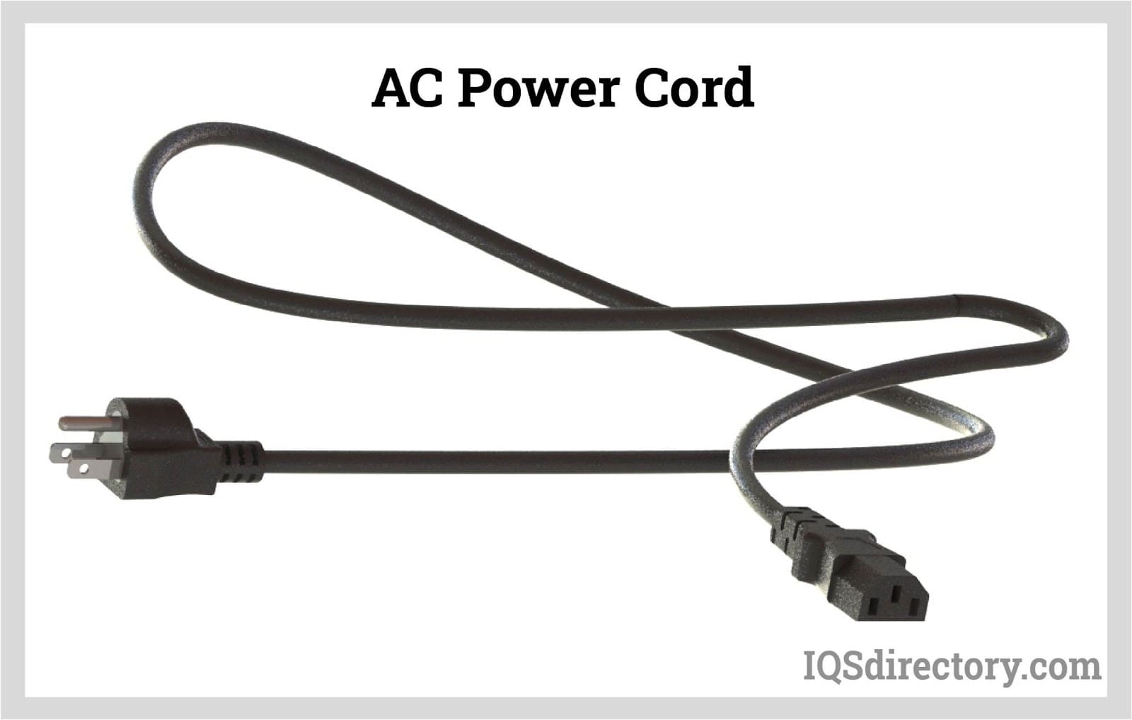
An AC power cord is a detachable way of providing an alternating current of electric energy from a mains power supply to an electrical appliance or equipment. Serving industries like...
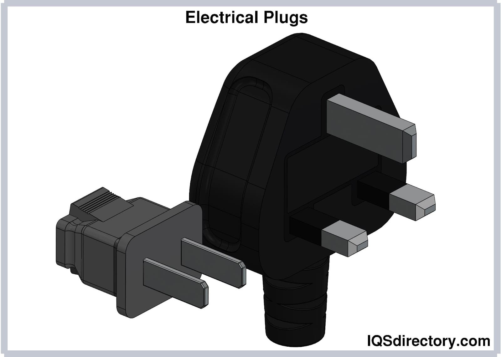
Electrical plugs, commonly known as power plugs, are devices responsible for supplying and drawing current from a receptacle to the circuitry of an electrical appliance...
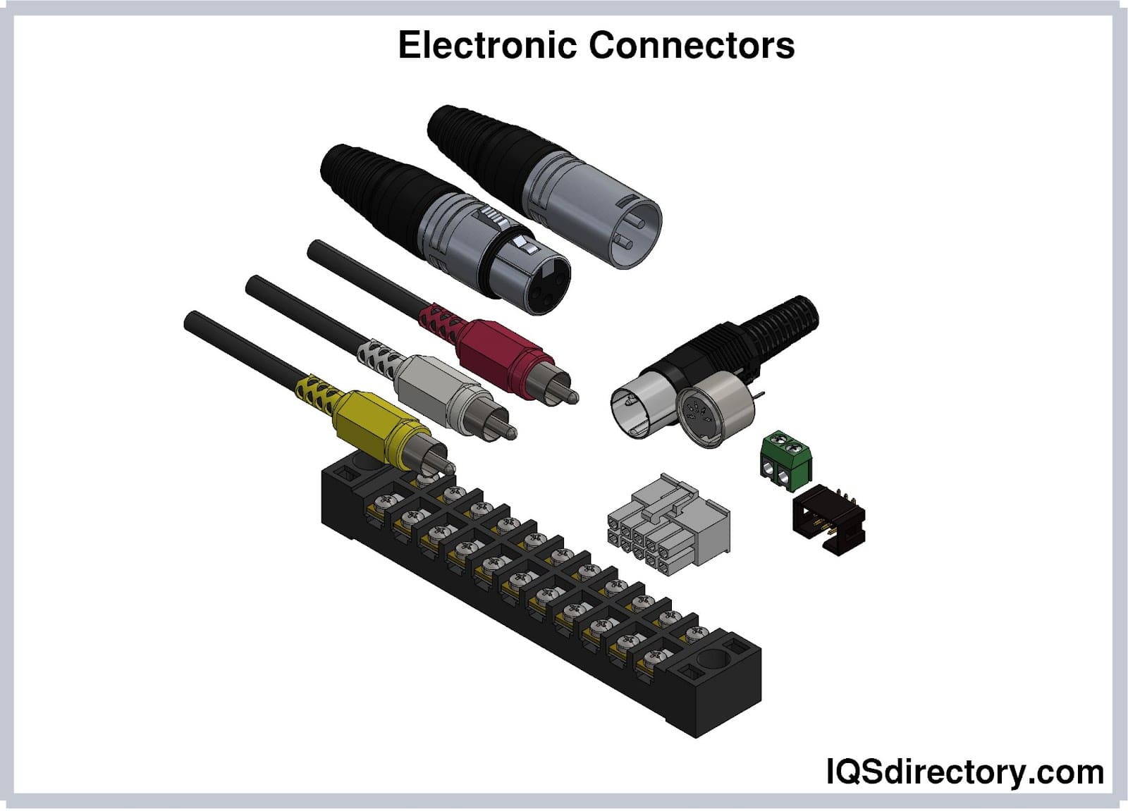
Electronic connectors are devices that join electronic circuits. They are used in assembling, installing, and supplying power to electrical devices. Connectors are an important component of every electronic equipment used in...
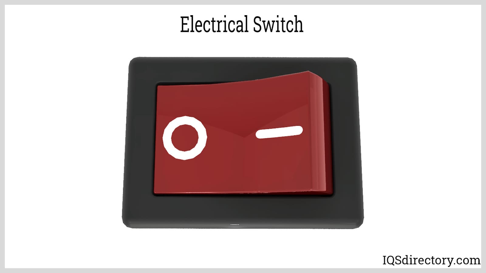
An electric switch is a device – usually electromechanical – that is used to open and close an electric circuit. This disables and enables the flow of electric current, respectively...
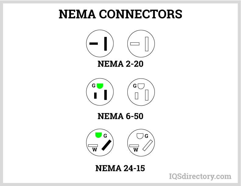
A NEMA connector is a method for connecting electronic devices to power outlets. They can carry alternating current (AC) or direct current (DC). AC current is the typical current found in homes, offices, stores, or businesses...
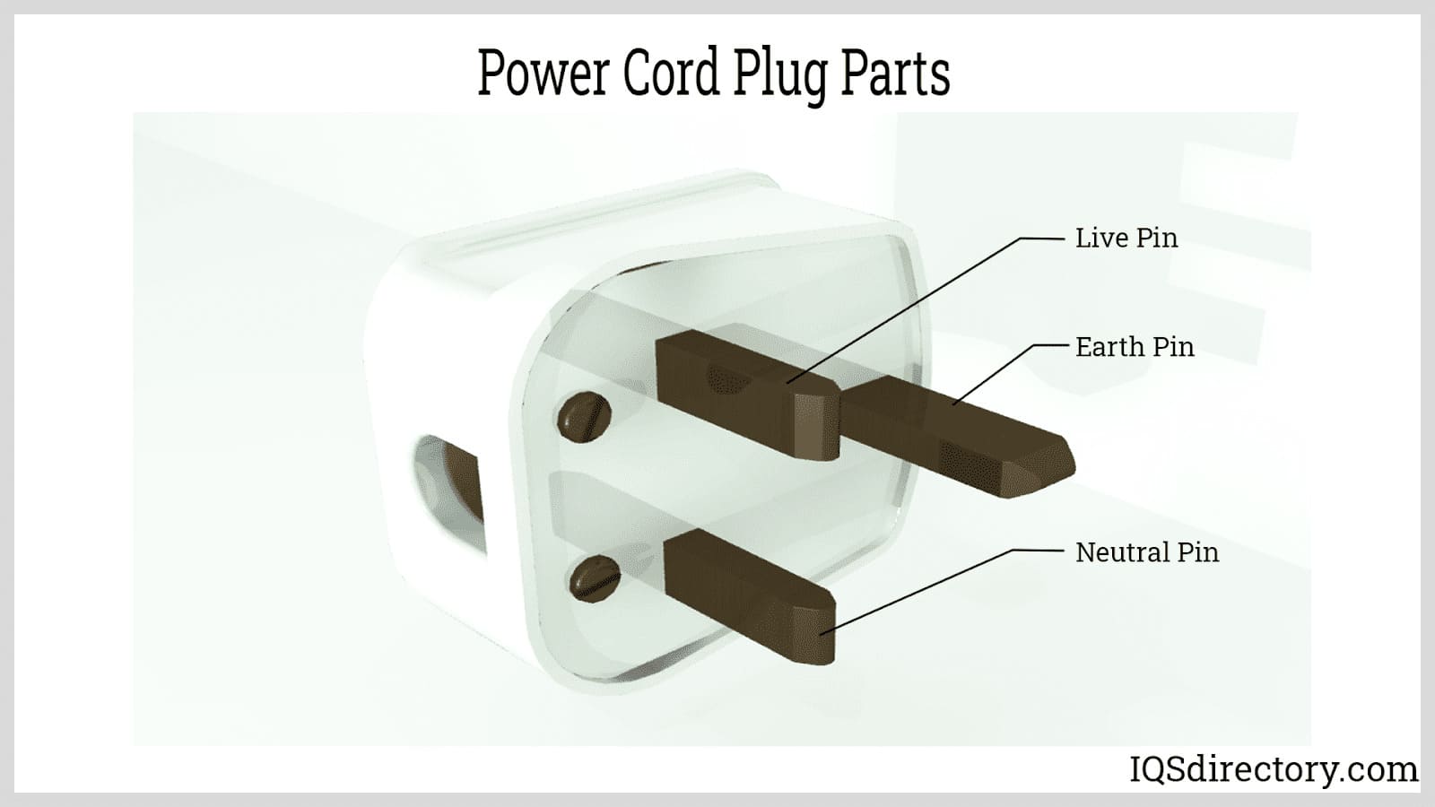
A power cord is an electrical component used for connecting appliances to an electrical utility or power supply. It is made from an insulated electrical cable with one or both ends molded with connectors...
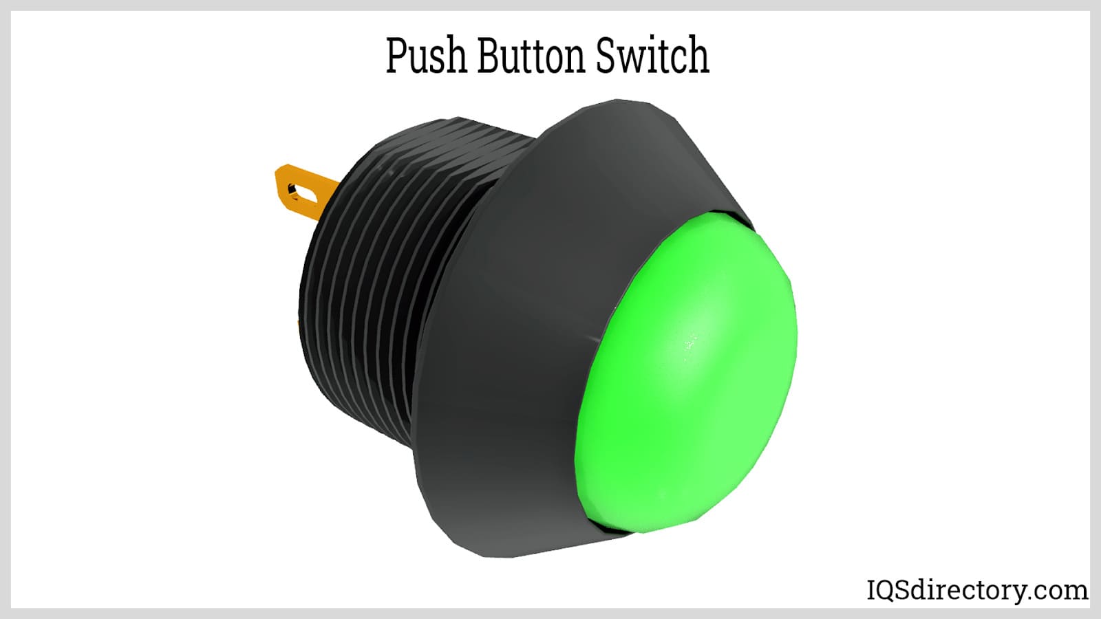
Push button switches are electrical actuators that, when pressed, either close or open the electrical circuits to which they are attached. They are capable of controlling a wide range of electronic gadgets...
Thomas Edison developed the power distribution system in 1882. He wrapped a copper rod in jute, a soft shiny fiber from plants, as an insulator. The jute wrapped copper rod was placed in a pipe with a bituminous compound...