Pressure Tanks
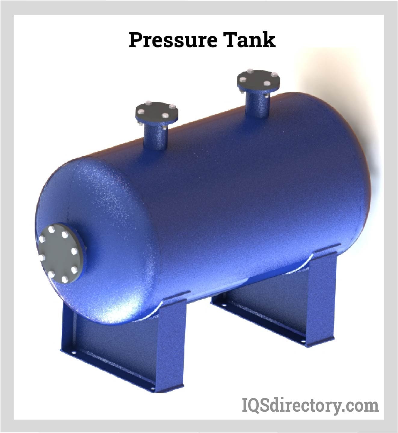
Pressure tanks are vessels that are used to store, hold, and/or convey gasses, vapors and fluids at pressures greater than atmospheric pressure, also known as high pressures...
Please fill out the following form to submit a Request for Quote to any of the following companies listed on
This article presents all the information you need to know about Pressure Vessels. Read further and learn more about:
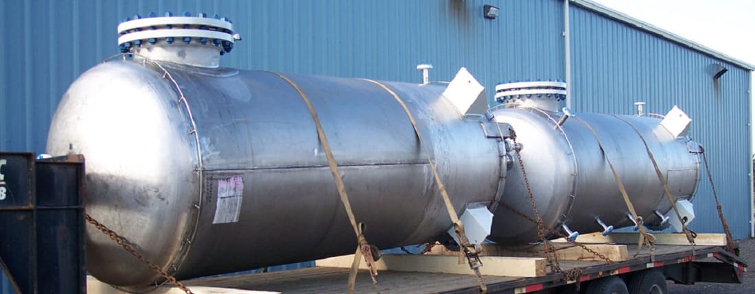
Pressure vessels are enclosed structures designed to hold liquids, gases, or vapors at pressures significantly differing from the surrounding atmosphere. They play a crucial role across diverse industries, such as petrochemical, oil and gas, chemical processing, and food manufacturing. Typical examples include reactors, flash drums, separators, and heat exchangers.
Pressure vessels must adhere to several standards and regulations. The ASME Boiler and Pressure Vessel Code (BPVC) is highly regarded, offering detailed guidelines for the design, construction, installation, testing, inspection, and certification of boilers, pressure vessels, and nuclear plant components. Specifically, ASME BPVC Section VIII specializes in pressure vessels and is segmented into three parts:
Another significant standard is the API 510 - Pressure Vessel Inspection Code: In-Service Inspection, Rating, Repair, and Alteration. This standard emphasizes the ongoing maintenance, inspection, and repair of operational pressure vessels, ensuring their sustained integrity and safety.
Pressure vessels must be operated within prescribed safety parameters, like maximum allowable working temperature and pressure. All operations involving pressure vessels should be conducted by certified professionals, as any accidental release or leakage could present substantial hazards to the environment.
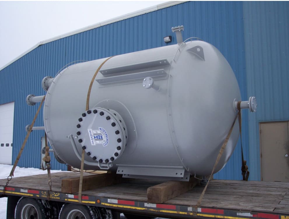
Pressure vessels can be categorized based on their function or geometric shape.
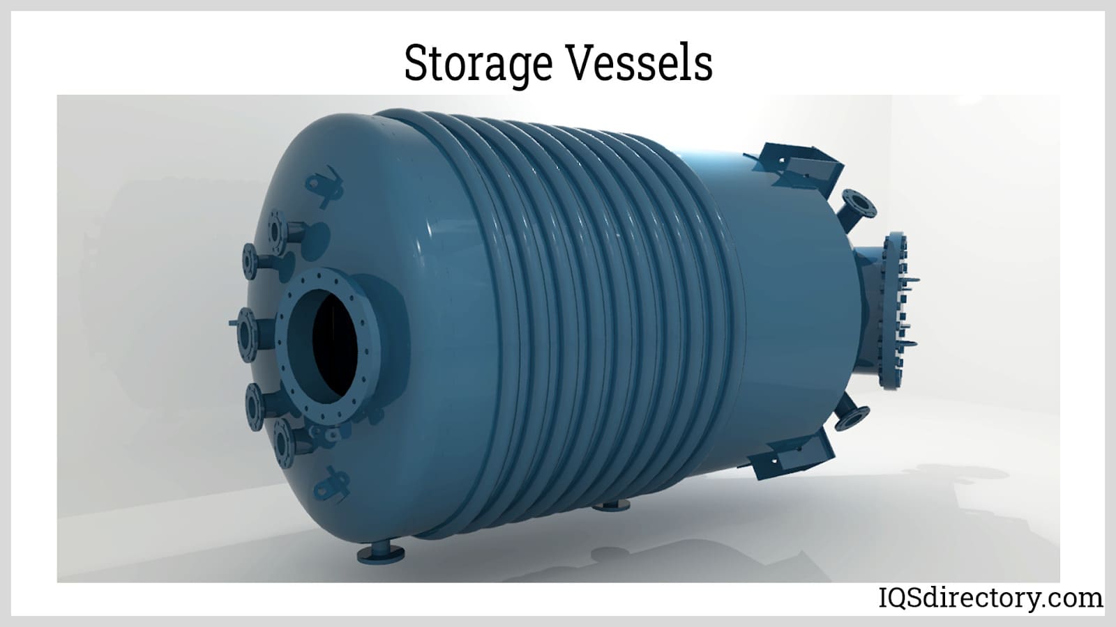
Storage Vessels: Storage vessels are pressure vessels that temporarily hold liquids, vapors, and gases. The vessel may be used to contain fluids in a later process, or for storing finished products such as compressed natural gas (CNG) and liquid nitrogen.
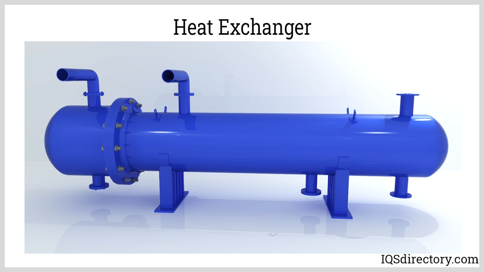
Heat Exchangers: Heat exchangers are used to transfer heat between two or more fluids. They are commonly used in the food, pharmaceutical, energy, and bioprocessing industries. The operation of heat exchanger equipment depends on the thermal and flow properties of the fluids involved in heat exchange, and on the thermal property of the conductive partition (for indirect contact heat exchangers). Materials in a heat exchanger experience stress from the temperature difference of the hot and cold fluids, and the internal pressure containing the fluids.
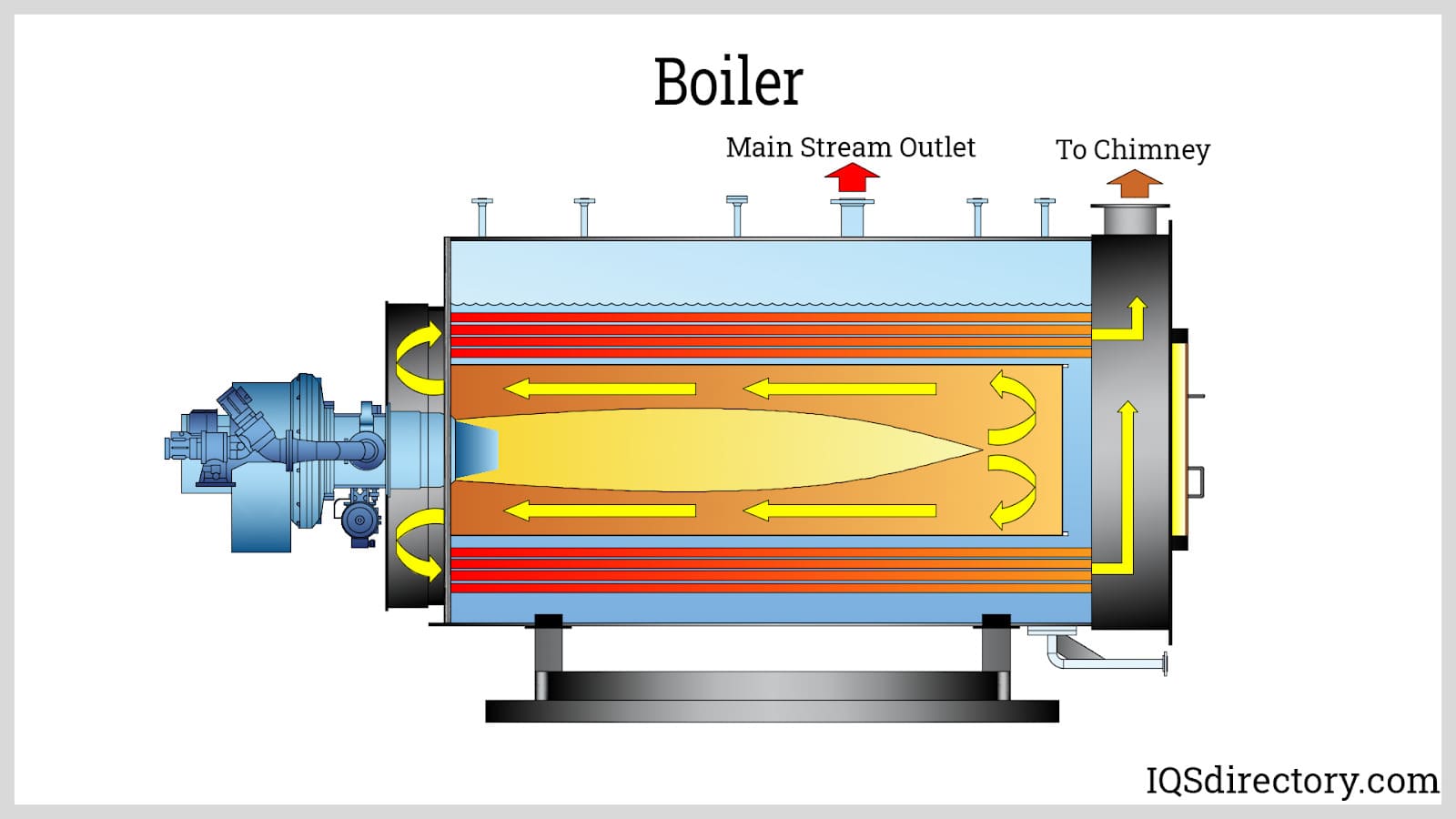
Boilers: Boilers are heat transfer equipment that utilizes fuel, nuclear or electrical power as sources of heat. They are typically composed of an enclosed vessel that allows heat transfer from the source to the fluid. They are primarily used to heat liquids. Oftentimes, phase transformation of the fluid from liquid to vapor phase occurs inside the boiler. The vapor generated by the boiler is used for various heating applications and in power generation. Steam boilers generate steam at an elevated pressure to accelerate the blades of the turbine. Hence, the boiler vessel must have high strength to endure such high pressures and thermal stress. For the majority of materials, strength decreases with increasing temperature.
Process Vessels: Process vessels are a broad classification of pressure vessels. These are containers where industrial processes occur, such as mixing and agitation, decantation, distillation and mass separation, and chemical reaction. The change in the internal pressure of a process vessel depends on the nature of the process carried out and the transformation of the substances involved. Among the special types of process vessels are the following:
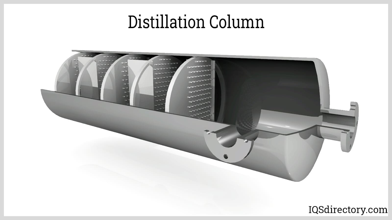
Distillation columns allow the separation of a mixture of liquids based on the difference in their volatilities. There are two types of distillation processes. The type of distillation process will greatly influence the design of the pressure vessel:
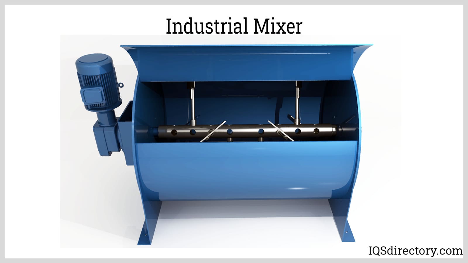
Industrial mixers are pressure vessels that are equipped with motor-powered blades to homogenize and emulsify a single or multiple substances. The substances mixed may be a pure liquid mixture, a semi-solid mixture, or a solid-liquid mixture. Agitating equipment operates at varying speeds depending on the extent of homogeneity. The mixing tank may be subjected to elevated temperatures and pressures, depending on the final product requirements.
As the reactants are converted into products, the internal pressure increases if gaseous products are generated and increases even more at higher temperatures.
The following are the types of chemical reactors which utilize a pressure vessel:
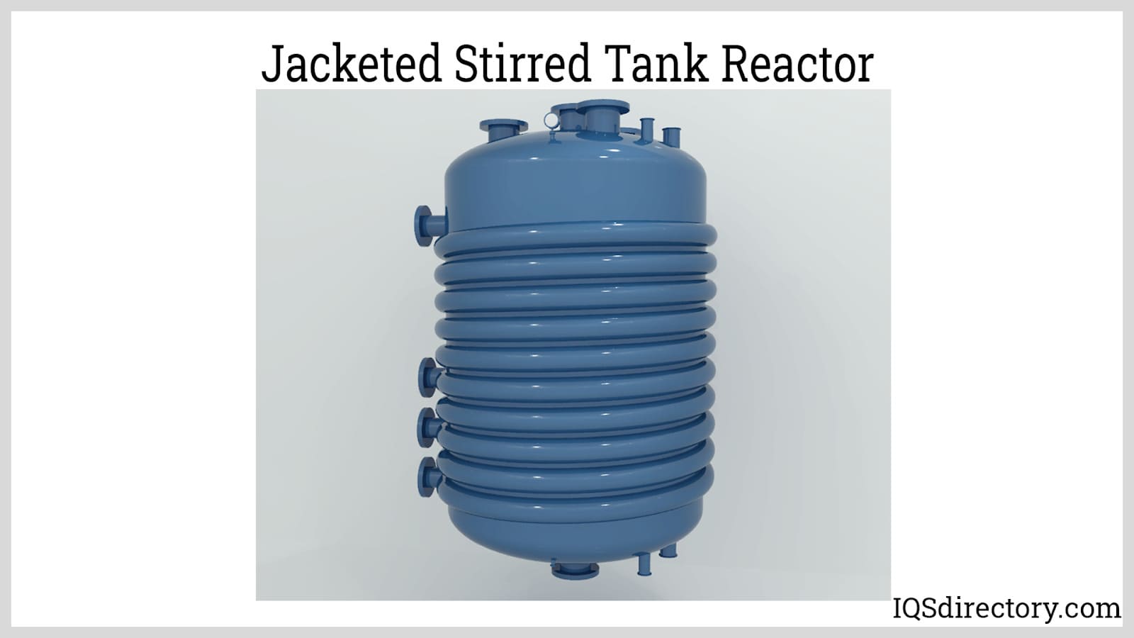
Jacketed reactors maintain the temperature of the reactants, products, and catalysts during a chemical reaction. A utility fluid (e.g., cooling water, steam) flows through the jacket that wraps around the vessel to cool or heat the contents of the reactor.
The nature of the reaction is a critical consideration in designing reactors. Heat may be released (exothermic reaction) or absorbed (endothermic reaction) during a chemical reaction. Cooling or heating is important to provide favorable conditions for the reaction, thus maximizing product conversion and increasing efficiency, and to prevent uncontrolled increase or decrease in temperature during the reaction. Therefore, a jacketed reactor must be considered.
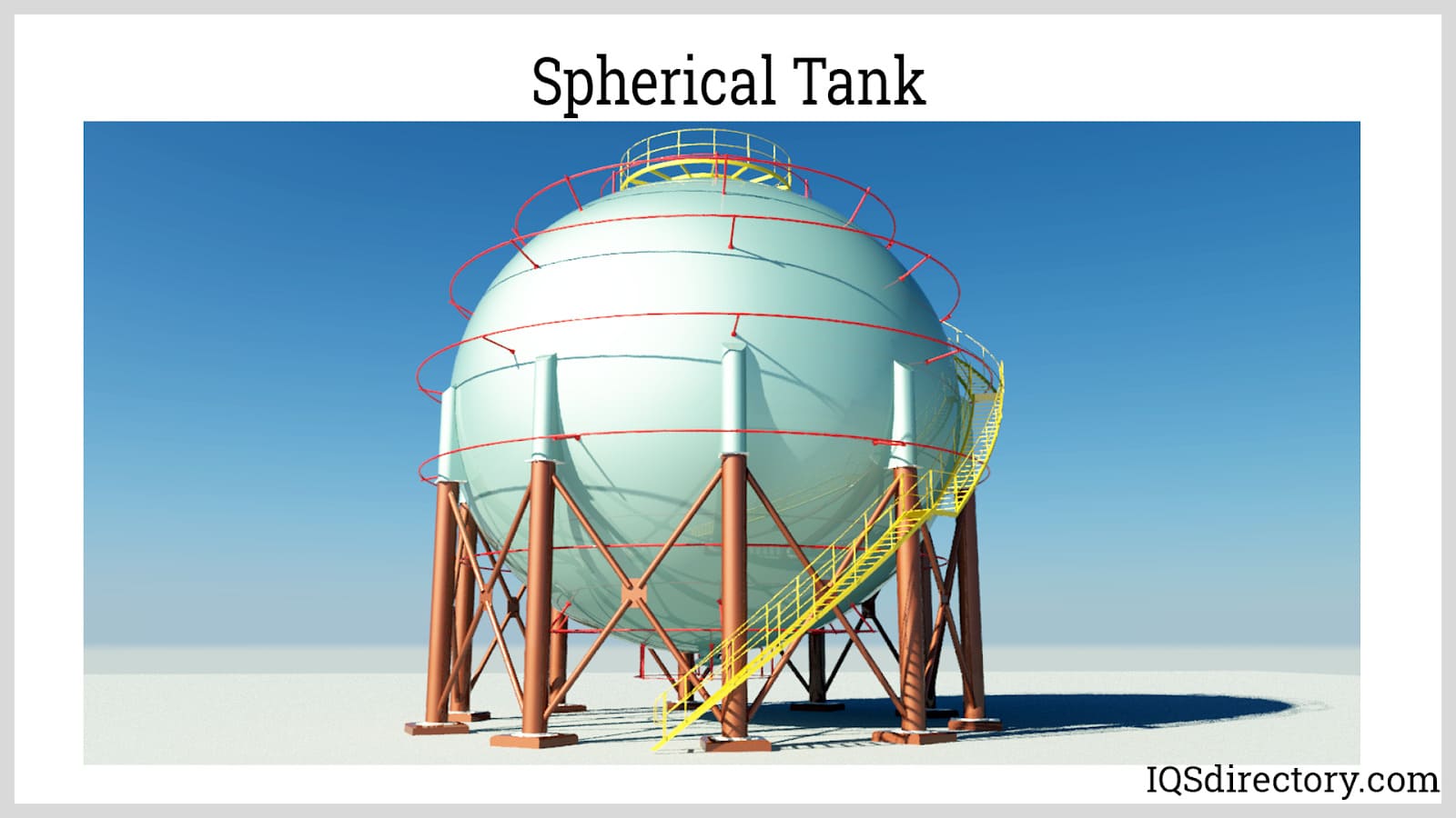
Spherical Pressure Vessels: Spherical pressure vessels are ideal for containing high-pressure fluids due to their strong structure, but they are difficult and expensive to fabricate. The internal and external stress is evenly distributed on the sphere‘s surface, which means there are no weak points. They have a smaller surface area per unit volume. Spherical vessels will consume less amount of material than the cylindrical vessel if a pressure vessel of the same volume will be fabricated. The smaller surface area of the spherical vessel will also have less heat transfer from the hotter body compared to other shapes.
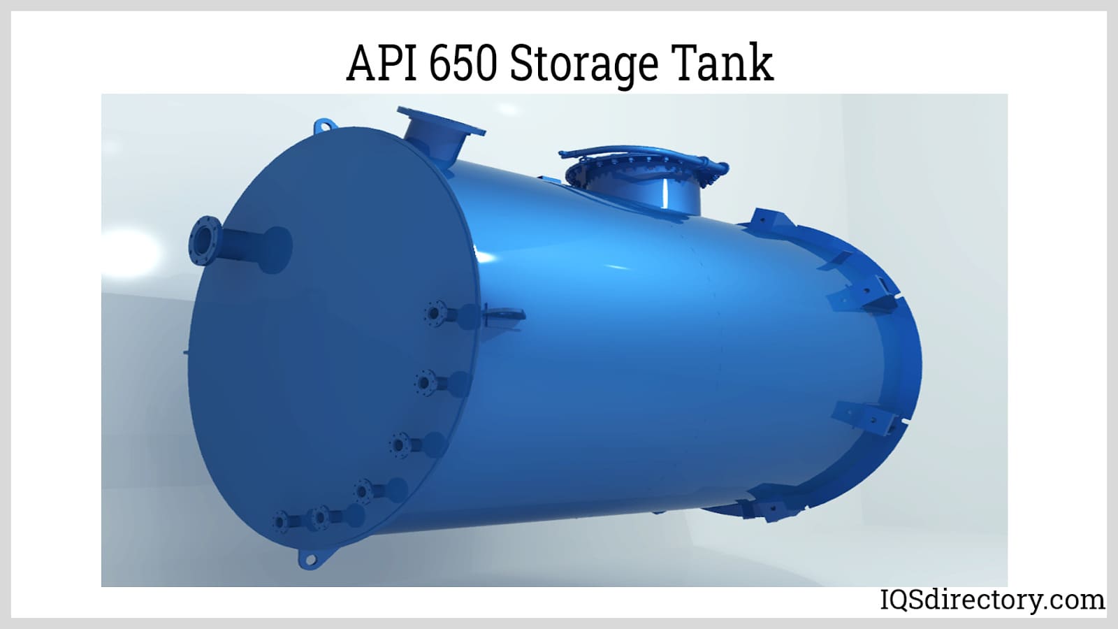
Cylindrical Pressure Vessels: Cylindrical pressure vessels are composed of a cylindrical shell and a set of heads. The cylindrical shell is the body of the pressure vessel. The heads serve as the end caps or enclosure to the shell to cover the contents of the vessel. The heads may have a flatter or more rounded profile. The latter reduces the weakness of the cylindrical vessel.
Cylindrical pressure vessels are the most widely used vessel shape due to their versatility. They are much cheaper to produce than spherical vessels. However, they are generally weaker than spherical pressure vessels. They typically require thicker walls to achieve the same strength of spherical vessels bearing the same internal pressure.
The following are the types of pressure vessel heads:
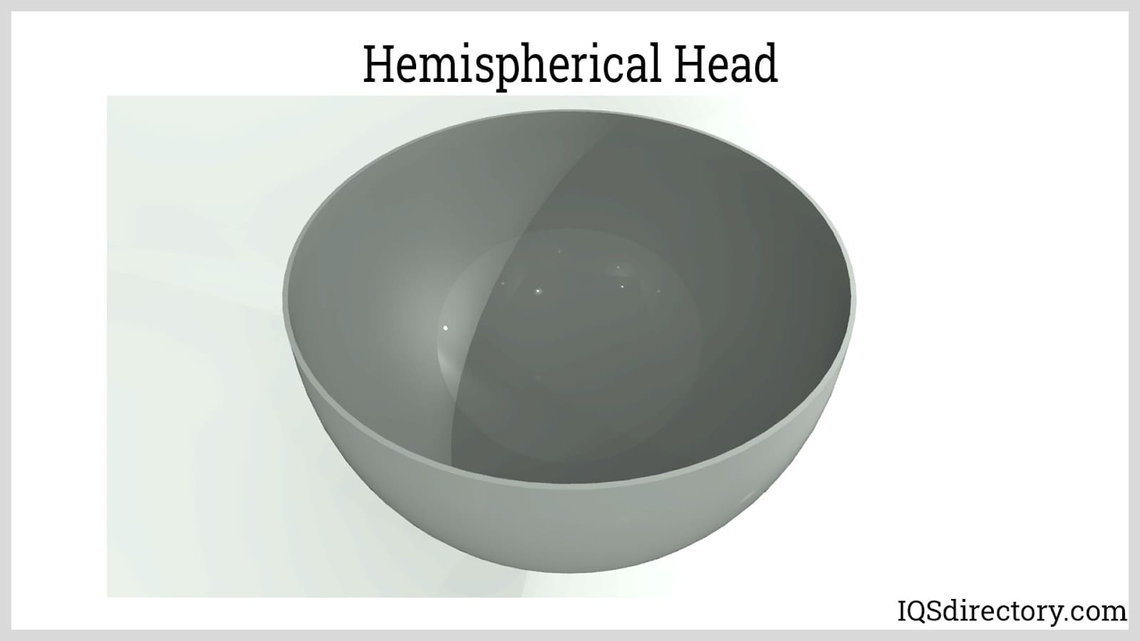
Hemispherical heads are ideal in handling high-pressure fluids and enclosing large-diameter vessels because the pressure is distributed equally across the head‘s surface. They have simple radial geometry and higher internal volume, but they are more difficult to fabricate and join to the shell. Compared to other head geometries, hemispherical heads require the least wall thickness that will handle the same internal pressure. The radius of a hemispherical head is equal to the radius of the cross-section of the cylindrical vessel. The depth of the head is half of the diameter.
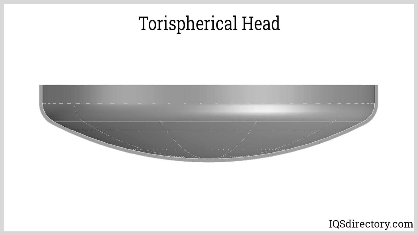
Torispherical heads are suitable for handling pressures less than 15 bars. They are the easiest and cheapest to fabricate among the heads. They are used for pressure vessels with height restrictions because of their flatter profile. They are formed from part of a torus and part of a sphere. The transition of the cylinder and the dish is called the knuckle that is in toroidal shape. The knuckle radius is equal to the radius of the torus, and the crown radius is equal to the radius of the sphere.
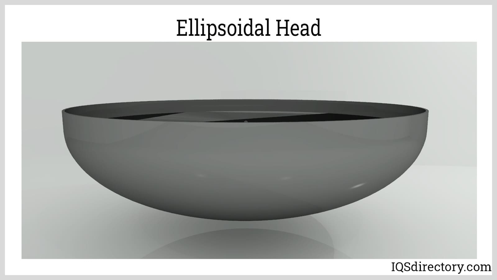
Ellipsoidal heads have a depth that is a fraction of the width of the head. Its radius varies between the major and minor axis, which is usually 2:1. The ellipsoidal head and its shell have the same wall thickness. This type of head is ideal for containing high-pressure gases due to its height-to-weight ratio. It can handle pressures greater than 15 bars. Ellipsoidal heads are resistant to pressure and have high overall strength, which makes them economical due to their reduced thickness requirement.
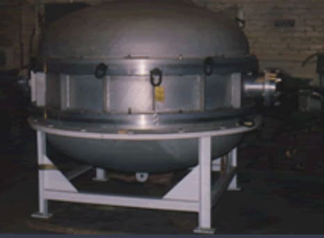
A cylindrical pressure vessel can be positioned with its axis either vertical or horizontal.
When choosing the right material for constructing pressure vessels, the following criteria should be considered:
Typical materials used in the construction of pressure vessels include:
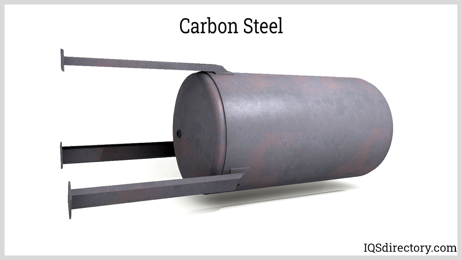
Carbon Steel: Carbon steel is a type of steel that has a higher carbon content of up to 2.5%. Carbon steel vessels are known for their high tensile strength for a minimal wall thickness, which is suitable for a wide range of applications. They are to impact and vibration. However, carbon steel is difficult to bend and form into shapes due to its high strength. It is also more susceptible to corrosion and rusting than stainless steel since it does not contain chromium.
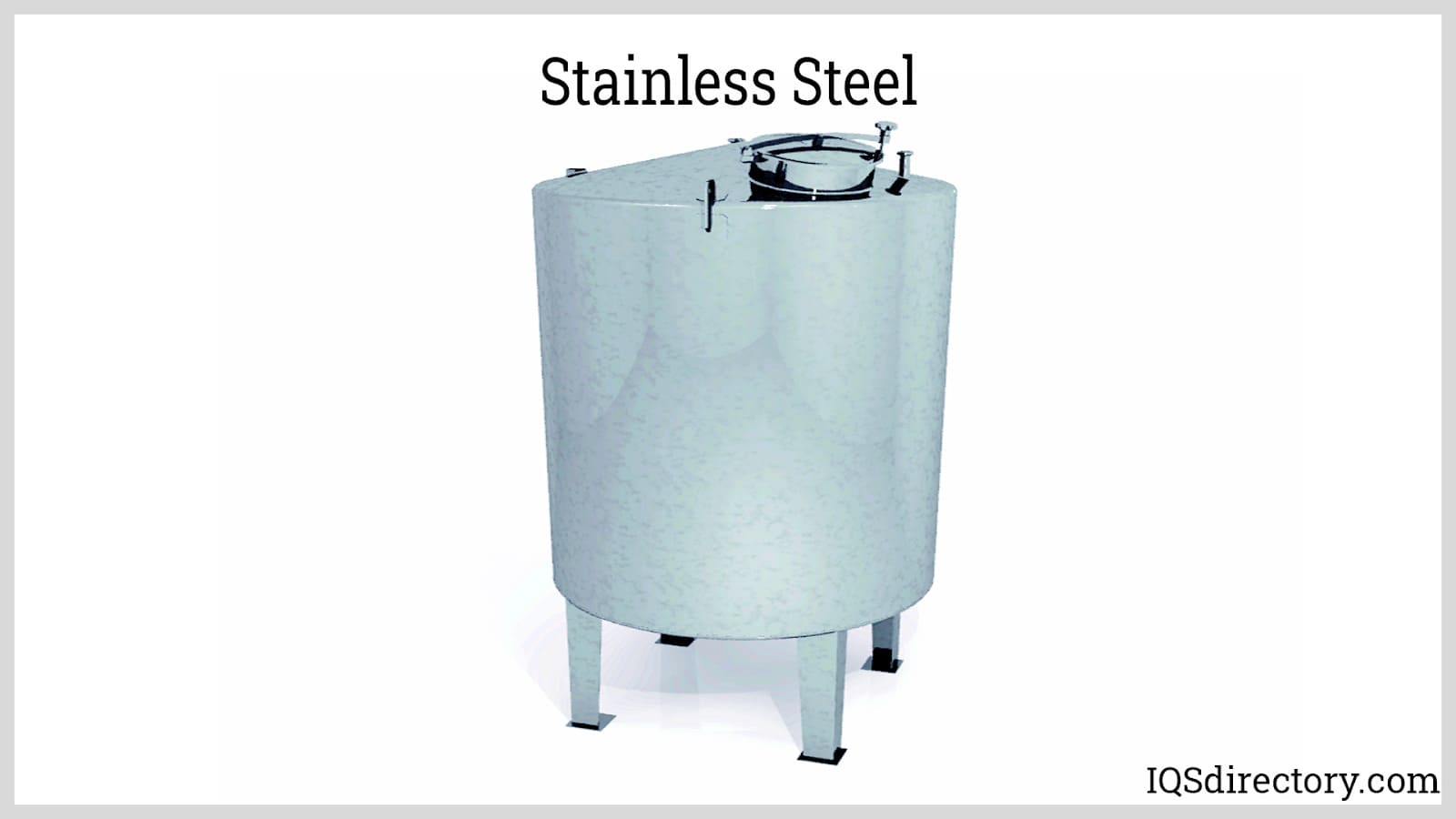
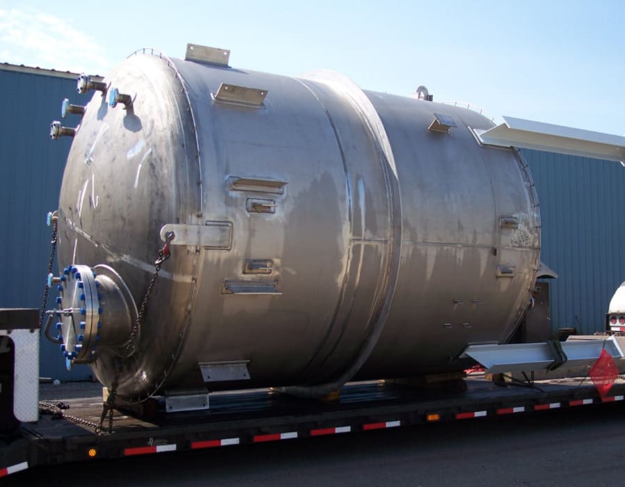
Stainless Steel: Stainless steel is a type of steel that has a higher chromium content of up to 10.5 – 30% and lower carbon content and trace amounts of nickel. They are known for their excellent chemical, corrosion, and weathering resistance which is attributed to their chromium content. A thin, inert chromium oxide film is formed at the surface to prevent oxygen diffusion to the bulk of the metal. Like carbon steel, it also exhibits high strength for a lower wall thickness. It is easier to form compared to carbon steel due to its increased ductility and elasticity.
Nickel Alloys: Nickel alloys offer good corrosion and weathering resistance, and protection against thermal expansion. The addition of chromium to the nickel alloy further increases its heat resistance. Pressure vessels constructed from nickel alloys are widely used in the oil and gas industry, cryogenic applications, and in other harsh environments. It also has a longer service life. However, it is difficult to work and has a higher fabrication cost. The purity of nickel alloys is important to protect their strength and reliability.
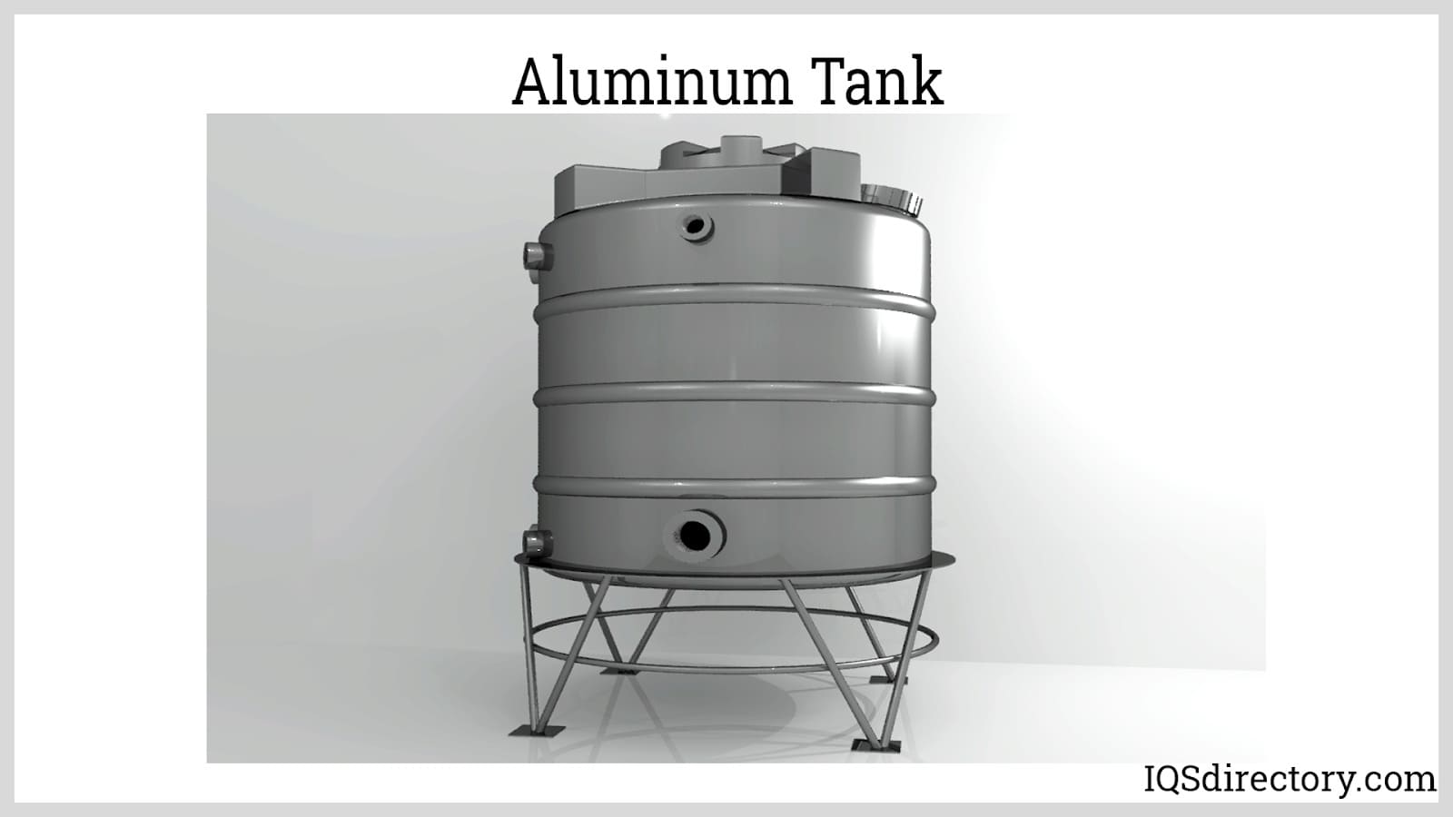
Aluminum: Aluminum is known for its high strength-to-density ratio, which means it has high strength and lightweight at the same time. It is cheaper and more fabricated than stainless steel. It also has good corrosion resistance. Aluminum vessels are commonly used in laboratory-scale applications. However, it is not suitable for high-pressure applications since it has less density, which is one-third of stainless steel.
In designing a pressure vessel, the following parameters are essential for determining the wall thickness of the shell and heads:
Design Pressure: The design pressure is a value in which the vessel specifications are calculated. It is derived from the maximum operating pressure, which is the anticipated surge in pressure during upset conditions such as start-ups, emergency shutdown, and process abnormalities. It is always higher than the maximum operating pressure. The pressure relief system of a vessel is also based on this parameter to minimize the risk of explosions. According to Towler, the design pressure should be overdesigned by 5-10% from the maximum operating pressure.
For vessels that potentially can experience vacuum pressure, the design pressure must be set to resist one full vacuum (-14.7 psig).
Maximum Allowable Working Pressure (MAWP): The MAWP is the highest permissible pressure measured at the top of the equipment at which the vessel must operate based on its design temperature. It is the highest pressure that the weakest part of the vessel can handle at its design temperature. MAWP value is designated by the American Society of Mechanical Engineers (ASME) and is used by industries to ensure that the vessel will not operate beyond this value to establish safety protocols and prevent explosions.
MAWP is different from the design pressure. MAWP is an extensive property that is based on the physical limitations of the material. Corrosion and wear lower the MAWP of the material. The design pressure, on the other hand, is based on the operating condition of the process, and it may be lower than or equal to the MAWP.
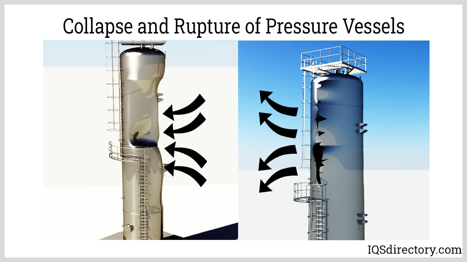
Design Temperature: The maximum allowable stress is highly dependent on the temperature, as strength decreases with increasing temperature and becomes brittle at very low temperatures. The pressure vessel should not operate at a higher temperature where the maximum allowable pressure is evaluated. The design temperature is always greater than the maximum operating temperature and lesser than the minimum temperature.
There are several rules of thumb in evaluating the design temperature. Towler suggests that the design temperature must be 50°F from the maximum operating temperature and -25°F from the minimum operating temperature. For Turton, a maximum allowance of 25°C must be given for vessels that will be operating between -30 to 345°C. The disturbances that have a drastic influence on the temperature of the pressure vessel must be considered by the designer.
| Category A | Longitudinal or spiral welds in the main shell, necks or nozzles, or circumferential welds connecting hemispherical heads to the main shell, necks or nozzles. |
| Category B | Circumferential welds in the main shell, necks or nozzles or connecting a formed head other than hemispherical. |
| Category C | Welds connecting flanges, tubesheets or flat heads to the main shell, a formed head, neck or nozzle. |
| Category D | Welds connecting the communicating chambers or nozzles to the main shell, to heads or to necks. |
The joint efficiency is the ratio of the strength of the welded plate to the strength of the unwelded virgin plate. Generally, the strength is lower at the welded joint. Welded joints without further inspection and radiographic testing are assumed to be weaker due to defects such as porosity are potentially present. Joint efficiencies allowed under ASME BPV Code Sec. VIII D.1 is summarized in the table below:
| Joint Description | Joint Category | Joint Efficiency (Based on degree of radiographic examination) | ||
|---|---|---|---|---|
| Full | Spot | None | ||
| Double-welded butt joint or equivalent | A, B, C, D | 1.0 | 0.85 | 0.70 |
| Single-welded butt joint with backing strip | A, B, C, D | 0.9 | 0.8 | 0.65 |
| Single-welded butt joint without backing strip | A, B, C | NA | NA | 0.60 |
| Double full fillet lap joint | A, B, C | NA | NA | 0.55 |
| Single full fillet lap joint with plug welds | B, C | NA | NA | 0.50 |
| Single full fillet lap joint without plug welds | A, B | NA | NA | 0.45 |
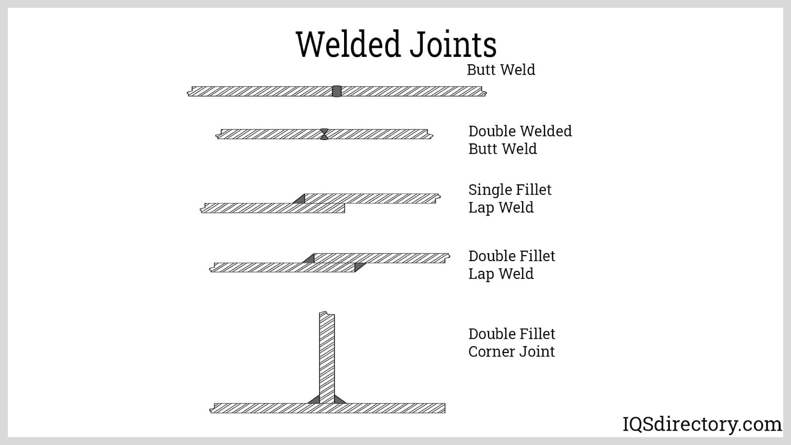
The vessel's shell and heads are fabricated by forging, rolling, and welding metal sheets. The wall thickness of these components is determined through detailed calculations, taking into account the previously mentioned factors. To ensure the pressure vessel functions effectively, various auxiliary equipment, devices, and accessories are also installed:
Post-weld heat treatment is performed to alleviate stresses induced during the welding and forming processes.
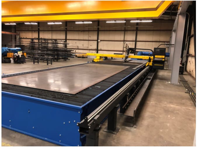
Pressure vessels can be fabricated either on-site or in a shop. Field-erected pressure vessels are too large to be assembled in a workshop and transported as a whole, so their parts are individually fabricated in a shop and then transported to the installation site. Assembly, welding, finishing, and accessory installation occur on-site. In contrast, shop-erected pressure vessels are smaller and can be fully assembled within a manufacturing facility. Once assembled, these vessels are transported to the site where only the installation of piping and minor adjustments are needed. The major phases of fabrication are completed in the shop before the vessel is delivered.
To verify the reliability of a pressure vessel, the following testing methods are utilized:
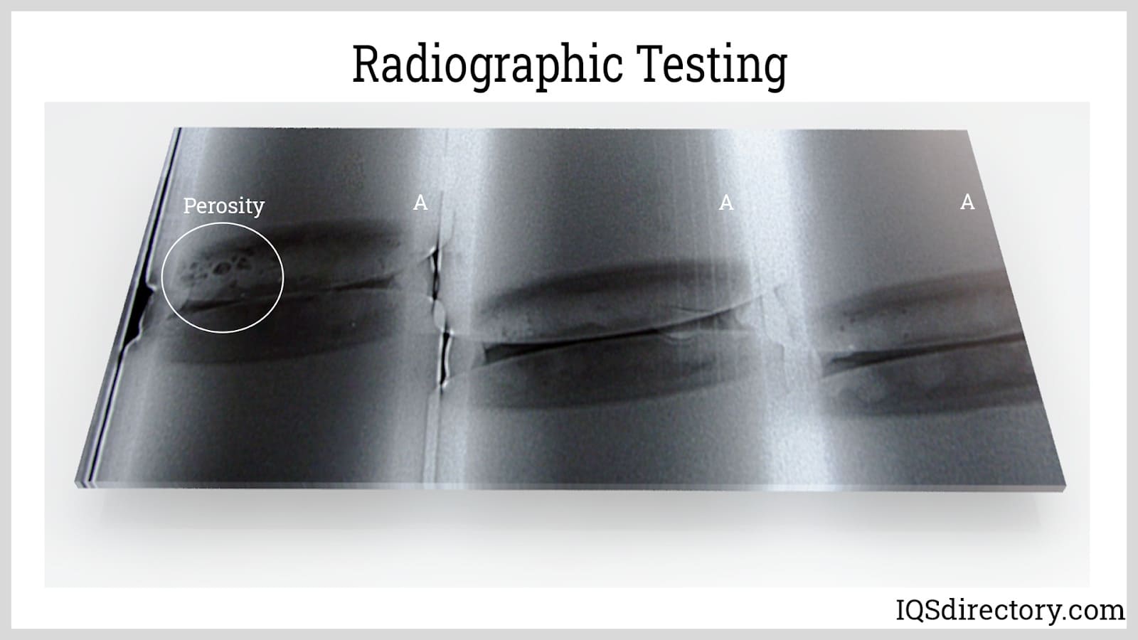
Radiographic Testing utilizes x-rays or gamma rays to produce an image of a pressure vessel‘s surface and subsurface. The reflected rays will be distorted once it passes any discontinuities, holes, and difference in density and will be exposed in the film. Radiographic testing is highly reproducible and requires minimal surface preparation. However, it is more expensive and requires a highly skilled operator to handle ionizing radiation.
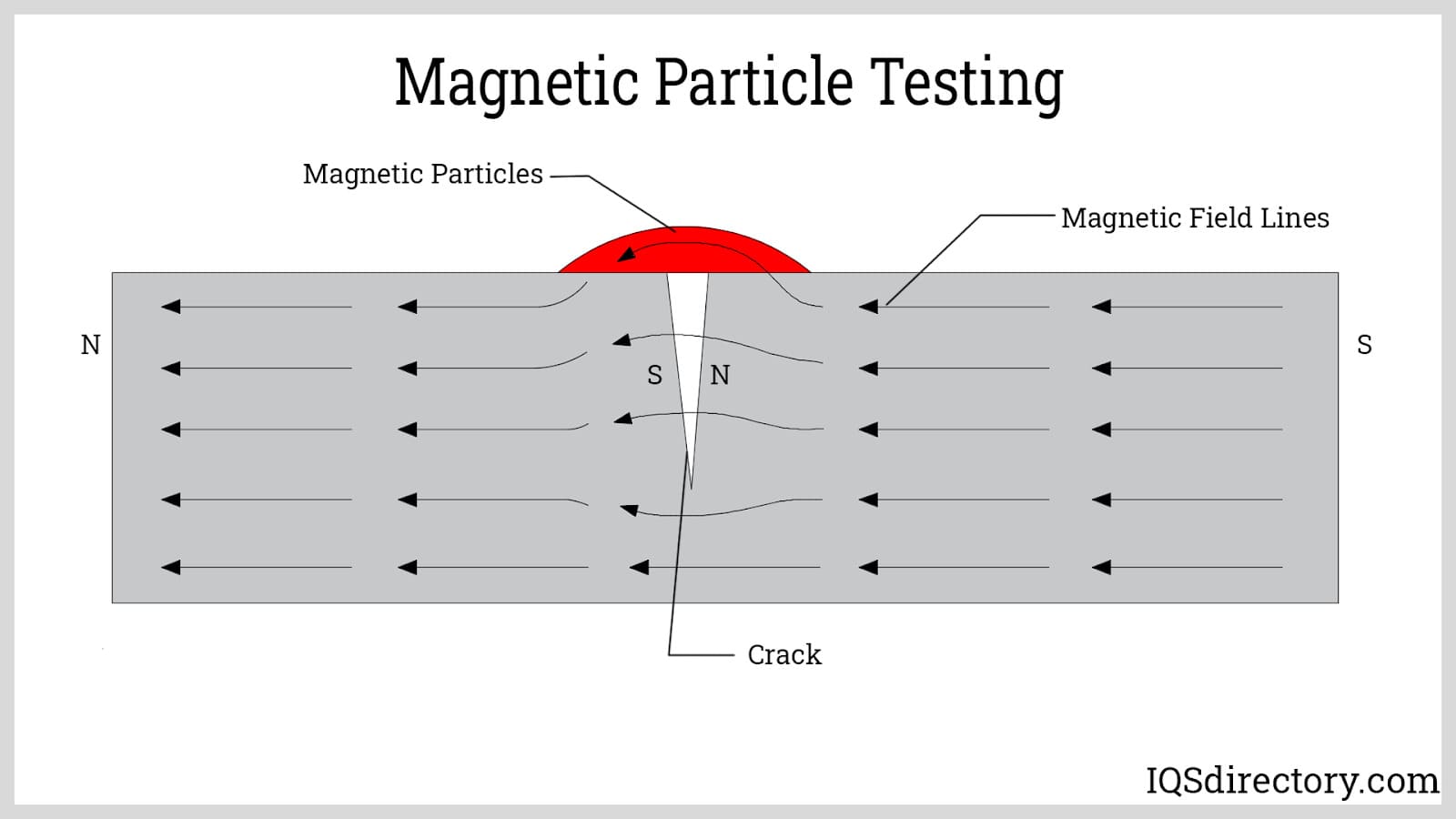
Magnetic Particle Testing uses magnetic current to detect discontinuities on the surface in ferromagnetic materials. The inspector runs a magnetic current through the pressure vessel between two probes. If the material is defect-free, the magnetic flux flows through the material without any interruption. However, if cracks or any other imperfections are present, the magnetic flux leaks out of the material. The imperfection will be more visible once ferromagnetic particles, either in a liquid suspension or powdered form, are applied to the vessel.
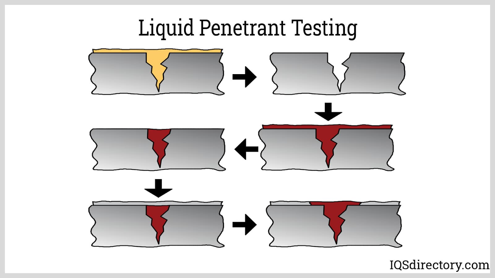
Liquid Penetrant Testing is commonly used on welded seams and plates. The inspector applies a small amount of liquid, called the penetrant, to an area with a possible flaw. The penetrant is allowed to settle after spraying and then wiped to clean the excess penetrant on the surface. The developer is then applied to reveal the penetrant that has seeped into the cracks.

Pressure tanks are vessels that are used to store, hold, and/or convey gasses, vapors and fluids at pressures greater than atmospheric pressure, also known as high pressures...
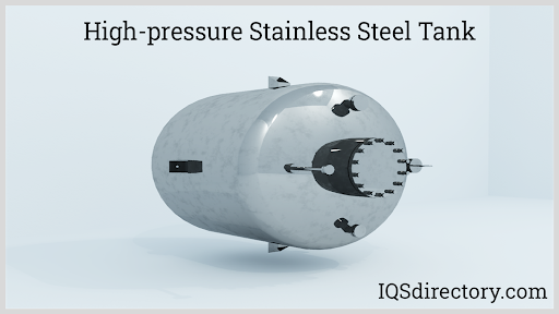
Stainless steel tanks are widely used in food, beverage, dairy, medicine, cosmetics, and other manufacturing processes where cleanliness and purity are important. These are also used in industrial plants for storing chemicals and gases where strong resistance from chemical degradation is required...