Diaphragm Valves
Linear motion valves utilize flexible closure elements like discs or diaphragms to control fluid flow, enabling precise regulation of the process stream based on the position of the open/close mechanism.
Diaphragm valves are a type of bidirectional linear motion valve. These valves manage, stop, and control fluid flow, and they also separate the flow stream from the closure element to ensure containment of contaminants, such as slurries, radioactive substances, corrosive fluids, or other specialized media. The diaphragm, a flexible and pressure-responsive component, operates by opening or closing the valve. It creates a seal when it connects to the valve body’s seat at the top.
The History of Diaphragm Valves
The use of diaphragm valves dates back to ancient Rome and Greece, where simple versions were used to control the water flow and temperature in their hot baths. These early valves were made of leather diaphragms that were manually closed over weirs to regulate the flow.
The modern diaphragm valve was patented in 1931 by P.K. Sanders. In the early 1900s, Sanders, a South African mining engineer, revisited the diaphragm valve concept from Roman baths as a solution to reduce costly power losses caused by leaking and failing seats in the valves used to supply underground air and water in South African mines.
The Hills McCanna Company became the first to manufacture the Saunders-patented diaphragm valve in the U.S., followed by Grinell (ITT Dia Flow), Dow Chemical, and Arco Winn. The introduction of elastomeric and plastic materials, such as PTFE diaphragms for valve lining, led to significant sales growth. The next key development was the need for a reliable actuator to automate the valve.
In the late 1940s, two brothers working in the photographic industry invented the reliable and innovative IDV (Iris Diaphragm Valve) flow control solution. They discovered that the powder and granular gelatin used in photographic film production would become sticky and clog traditional slide valves. The malfunctioning slide valve would leak, leading to difficult working conditions, slow response times, excess waste, and financial losses. The IDV was based on a simple principle: twisting the end of a balloon to prevent air from escaping. This diaphragm encapsulated product lumps, trapped particles, or dust, making it effective for a variety of applications.
The initial prototype of the 1940s was made from cotton shirtsleeves. As industries began using the IDV, it was produced in nylon and rubber, and later in Terylene and polyurethane-coated fabrics for pharmaceutical and food ingredient manufacturing. Non-corrosive materials, such as stainless steel and alloys, were used for sensitive or explosive products. Today, diaphragm solenoid valves, stainless steel solenoid valves, and sanitary diaphragm valves are also in production.
Diaphragm Valve Advantages and Disadvantages
-
Diaphragm Valve Advantages
Diaphragm valves offer several key advantages, including:
- They are exceptionally clean.
- They are ideal for challenging environments, such as those involving hazardous chemicals or radioactive fluids.
- They prevent contamination of the flow medium.
- They can function as both on/off and throttling-service valves.
- They feature leak-proof seals, eliminating stem leakage.
- They provide tight shut-off.
- They are easy to maintain, with repairs made without interrupting the pipeline.
- They help reduce leakage into the environment.
-
Diaphragm Valve Disadvantages
Despite their many advantages, diaphragm valves have some limitations:
- They are suitable only for moderate temperatures, typically between -60°F and 450°F.
- They are designed to operate at moderate pressures, generally up to 300 psi.
- They are not suitable for multi-turn operations.
Design of Diaphragm Valves
Diaphragm Valve Cost-Effectiveness
Diaphragm valves are more cost-effective because only the diaphragm and valve body need to be chemically compatible with the system fluid or media. The valve bodies can be made from solid alloys, metals, plastics, rubbers, or glass linings. Other valve components are sealed from the system to prevent contamination.
Diaphragm Valve End Connections
Diaphragm valve end connections come in a variety of forms, including butt welded, welded end sockets, threaded, flanged, or screwed. They may also feature clamp or grooved ends, solvent-cemented joint ends (for thermoplastic valves), or male sanitary threaded ends.
Rangeability
Rangeability refers to the type of valve determined by its minimum and maximum flow rate capabilities. It is calculated based on:
- The geometry of the valve (seat and closure design) and seat leakage (instability).
- The accuracy of the actuator near the valve’s closure.
- A valve with higher rangeability can control a wider range of flow rates. As the rangeability increases, sensitivity decreases near the closed position and increases as the valve opens.
Flow and Flow Coefficient
The flow coefficient determines the optimal valve opening size for the desired flow rate while maintaining control over the process fluid. It is defined as the number of gallons per minute (GPM) of 60°F water flowing through a valve at a specified opening with a 1 psi pressure drop across the valve.
Flow rate can be determined by:
- The linear method, where the flow rate is directly proportional to the disc travel.
- The equal percentage method, where the flow rate relates to the percentage change in valve opening during each incremental period.
Pressure Drop
The pressure drop, which is the change in pressure between the valve's inlet and outlet, helps determine the size of the valve opening. For example, if the pressure drop across the fully open valve is too small compared to the total system pressure drop, fluid flow will change minimally until the valve closes. This requires a fast-acting valve for greater control.
Valve Sizing for Throttle Devices
In throttle devices, the valve’s inlet and outlet ports are typically the same size because there is no pressure drop in an open/close system. The valve size is determined by the quantity of fluid or media passing through and the flow coefficient. To size the valve correctly, consider:
- The type of media being controlled (specific gravity and viscosity impact the flow rate), maximum inlet pressure, outlet pressure (drop), and the temperature at maximum load.
- The maximum capacity required for the system.
Types of Diaphragm Valves
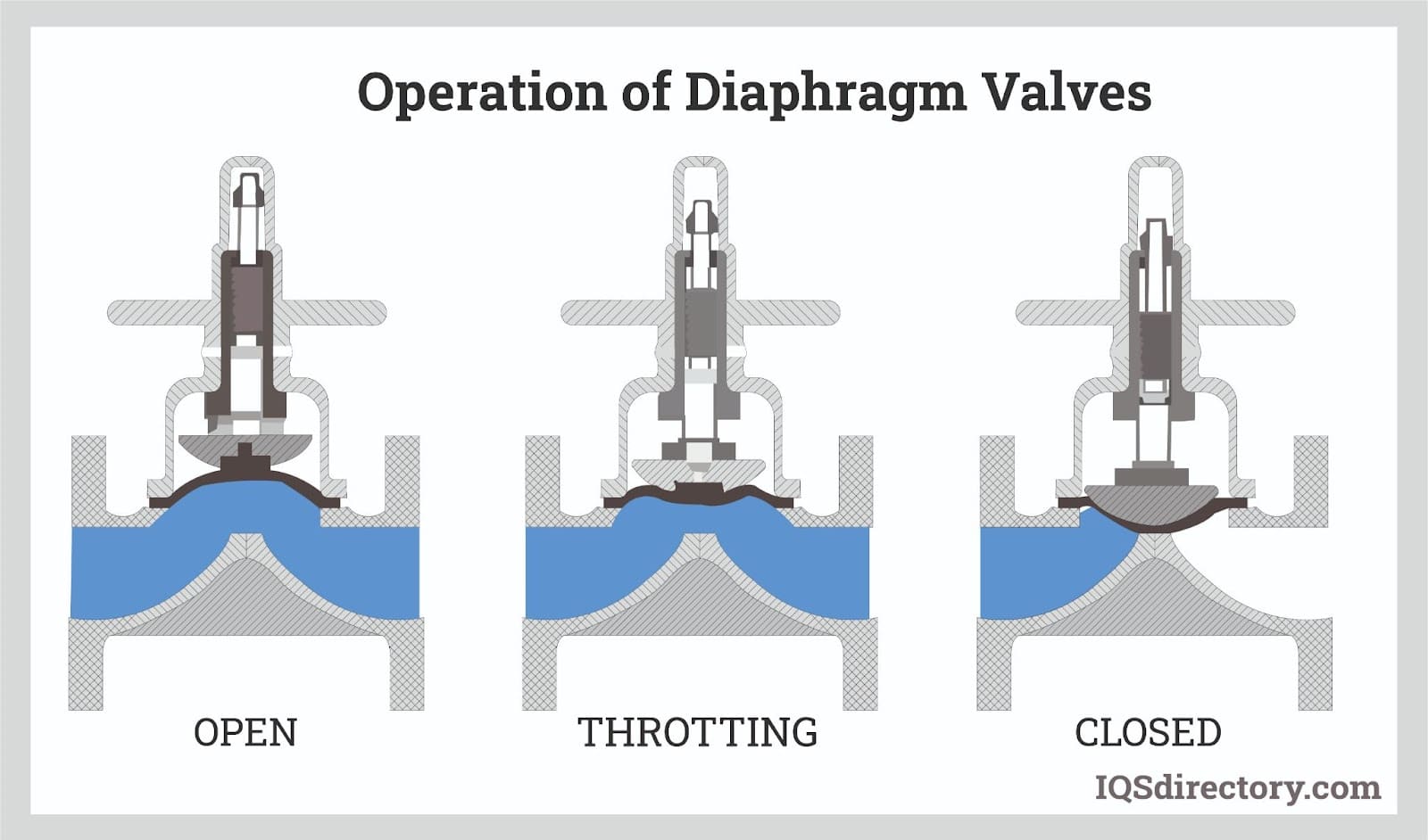 A diaphragm valve, is a valve with an elastomeric diaphragm and a seat upon which the diaphragm rests when it is closed which obstructs, controls, or isolates the flow of fluids.
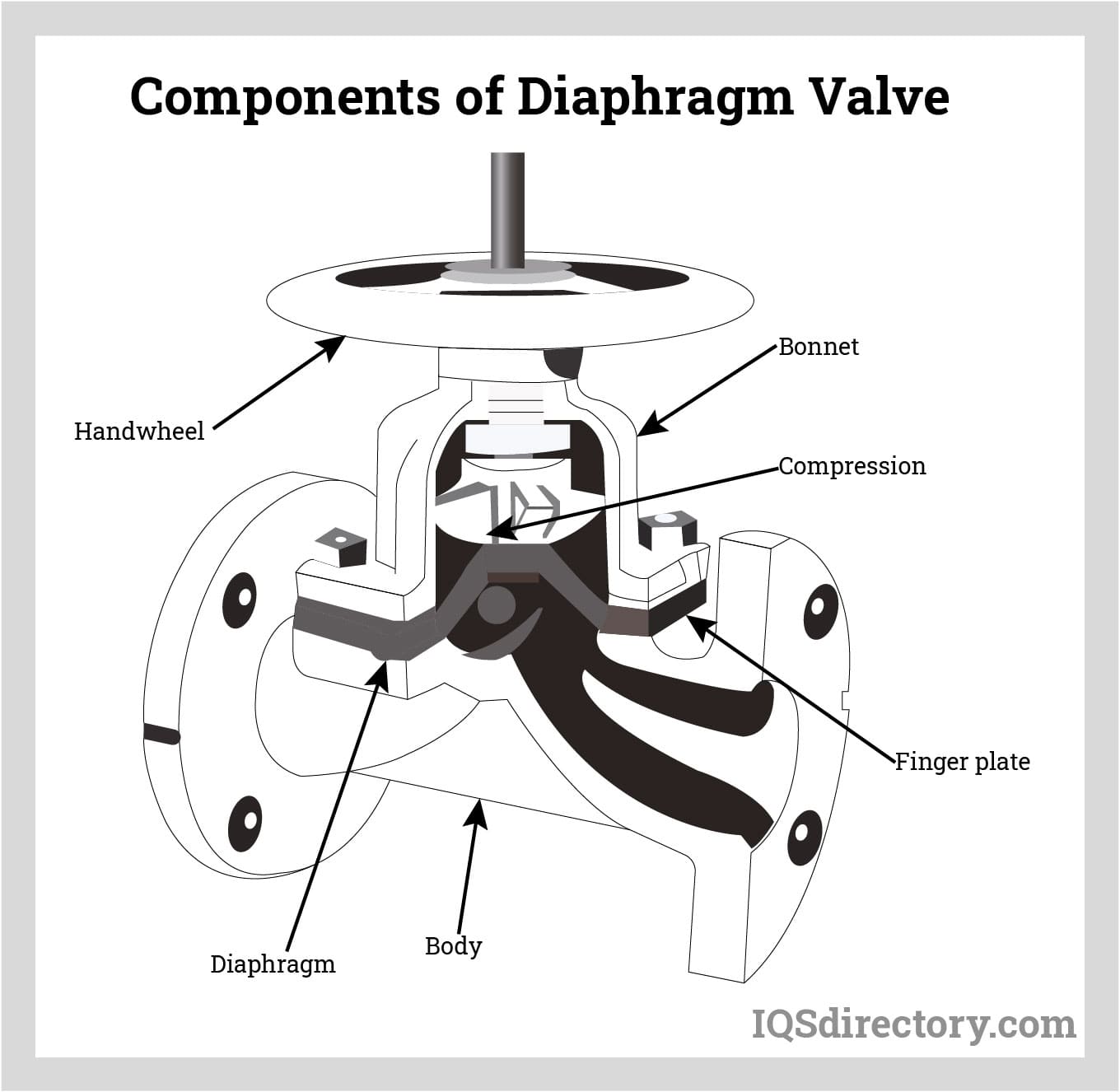 Diaphragm valves includes a stem, bonnet, compressor, diaphragm, and actuator which the material depends on the function of the valve.
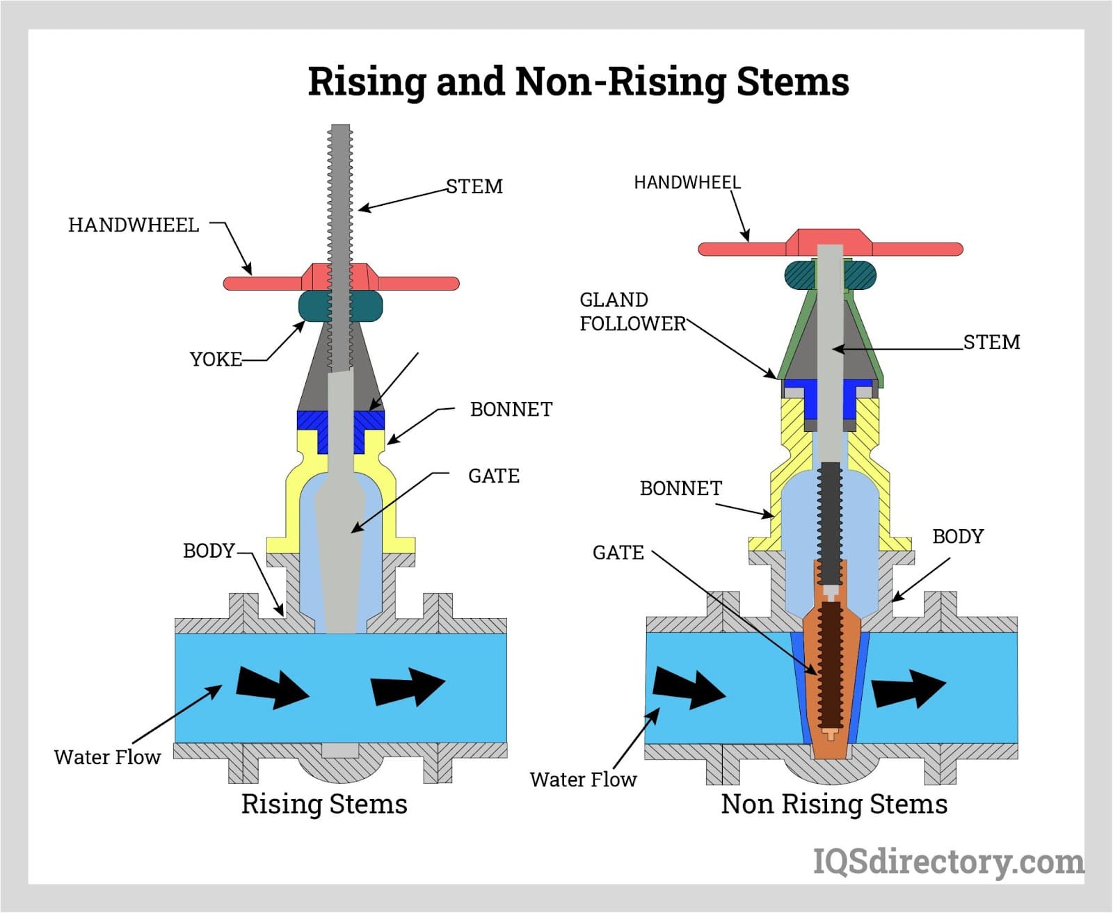 Rising stems, extend their length up to the handwheel, as the handwheel is turned the stem to open or close the valve. Non-rising stems rotate to open or close the valve without the stem move up or down.
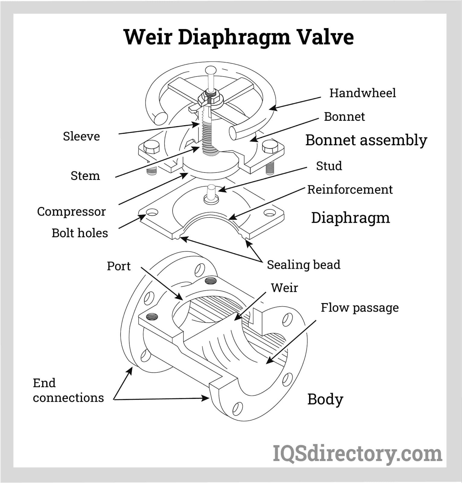 Weir diaphragm valves have a raised lip or saddle into which the diaphragm presses to create a sealing action.
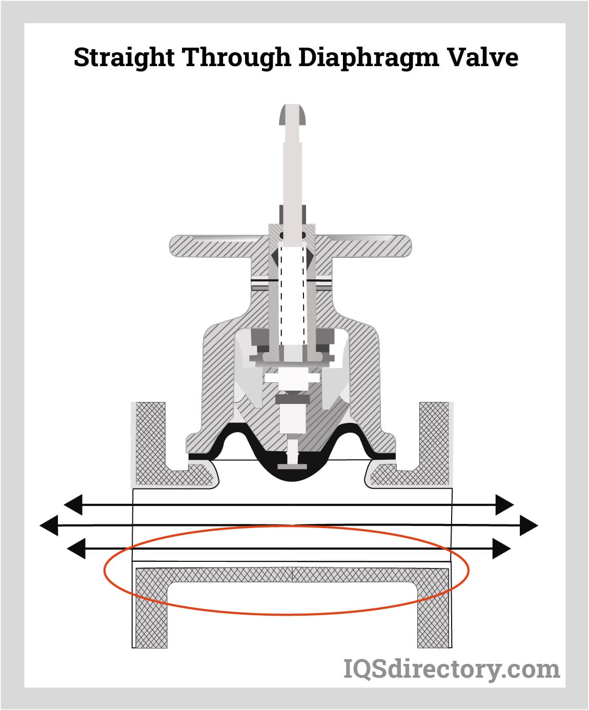 Straight through diaphragm valves have a flat bottom valve body to reduce the impediment of fluid flow giving the fluid a straight pathway.
Types of Diaphragm Valves
Diaphragm Valves Components: A diaphragm valve consists of:
- Rigid Body: The main structural part.
- Weir in the Flowpath: A raised structure where the diaphragm seals against.
- Flexible Diaphragm: Forms the valve’s upper pressure boundary and is essential for controlling flow.
- Compressor: A mechanism that forces the diaphragm against the weir to open or close the valve.
- Bonnet and Handwheel: These secure the diaphragm and actuate the compressor.
The valve’s rated design life and maximum pressure depend on the service temperature and diaphragm material. It's essential that the system's hydrostatic test pressure never exceeds the diaphragm's maximum pressure rating.
Types of Diaphragm Valves:
- Biotech Valves: Used in biotechnology fields such as agriculture, food science, and pharmaceuticals. These valves must meet sanitary standards.
- Diaphragm Check Valves: Maintain unidirectional flow in a process stream through a flexible membrane.
- Diaphragm Control Valves: Use a membrane to regulate flow in various operations, including controlling rate, pressure, temperature, and liquid levels.
- Diaphragm Diverter Valves: Redirect flow from one inlet to multiple outlets or vice versa.
- Diaphragm Tank Bottom Valves: Installed at the bottom of tanks to drain or sample fluids.
- Hygienic Valves: Designed for sanitary and aseptic applications.
- Plastic Diaphragm Valves: Use elastic polymeric membranes to regulate flow and pressure in plastic, metal, or composite forms.
- Pneumatic Diaphragm Valves: Use compressed air to engage a membrane, regulating the flow of the process stream.
- Process Valves: Any valve used to start, stop, or regulate the flow of materials.
- Straight-Through Diaphragm Valves: Designed for systems where the flow direction may change; they are ideal for slurries, sludge, and viscous fluids.
- Sanitary Diaphragm Valves: Constructed of sterile materials for aseptic liquid, gaseous, or semi-solid material flow.
- Tank Bottom Valves: Designed to eliminate dead zones where bacteria can accumulate.
- Weir Valves: Include a raised section (weir) where the diaphragm presses to form a seal, commonly used for controlling small flows in corrosive environments.
Variations of Weir-Type Diaphragm Valves:
- Full-Bore Valve: Used in the beverage industry, it allows cleaning without opening or removing the valve.
- Straightway Valve: Lifts the diaphragm for bidirectional flow and seals tightly when closed.
- Zero Static Valves: Multiport diaphragm valves that help with drainage and prevent process stagnation by reducing recesses where materials can get trapped.
Weir-Type Diaphragm Valve Features:
- Shut-off Area: The large shut-off area next to the seat makes it better for throttling compared to straight-through valves.
- Reduced Diaphragm Travel: The raised lip of the weir reduces diaphragm stress by minimizing travel between fully open and closed positions.
- Bonnet Assemblies: Recommended for handling hazardous gases or liquids in case the diaphragm fails, or for food processing where the body is self-draining.
These valves can be applied in various industries, including hazardous environments, food processing, and more, offering versatility, efficiency, and precision in flow control.
Valve Features
The diaphragm valve is designed with retaining rings at each end, and a flexible diaphragm is attached to a compressor, which is operated by the valve stem to regulate flow. The compressor’s movement starts or increases the flow, and one end of the valve is held in position while the other rotates 180 degrees to either stop or slow the flow. The rotation completely closes the opening, ensuring an even load support on the steel plate slide valve.
Valve Position Indicator
The valve’s position indicator shows whether the valve is in the on/off or open/closed position. This feature can be represented by various mechanisms such as switches, lights, stems, or visual indicators. For instance, piston indicators placed at the top of the valve ball indicate the direction of flow.
Valve Body
The construction of the diaphragm valve body is simple, and manufacturers size the valves based on their intended use. Diaphragm valves are available in a variety of materials, such as PVC, stainless steel, or lined with non-corrosive materials like lead, rubber, glass, plastic, or titanium, depending on the media they are designed to handle. Corrosive applications often require special materials to ensure durability and longevity.
The Stem
The diaphragm stem remains stationary and does not rotate. The "non-indicating stem" features a handwheel that rotates the stem bushing, engaging the stem threads. This movement drives the stem and attached compressor, which in turn, moves the diaphragm. Indicating stems, which are longer and extend through the handwheel, operate similarly to the non-indicating type but are equipped with a sealed bonnet and O-ring. Both systems use a sealed bonnet with a seal bushing for protection.
The Bonnet
The bonnet is attached to the valve body and covers the top portion of the valve. It houses the non-wetted parts of the valve, including the compressor and handwheel. The bonnet is lever-operated, quick to open, and interchangeable with the standard bonnet in weir-type valve bodies. Diaphragm valves used in vacuum services typically feature a 4" bonnet, with larger valves requiring a sealed, evacuated bonnet for optimal performance.
The Compressor
The compressor plays a crucial role in operating the diaphragm. It is round in shape and is positioned above the diaphragm and below the handwheel-stem assembly, ensuring proper functionality of the valve.
Travel Stops
Travel stops are adjustable components that prevent excessive diaphragm compression. The housing of the travel stops is tamper-proof, ensuring that the travel length remains set and prevents accidental adjustments.
Applications of Diaphragm
Diaphragm valves are often referred to as the "cleanest valves" due to their design, which minimizes contact between the fluid stream and the valve's working parts. This prevents contamination of the fluid and protects the operating mechanism from corrosion. As a result, diaphragm valves are commonly used in industries like food processing, pharmaceuticals, and water treatment.
Initially developed for industrial use, diaphragm valves have since been adapted for the bio-pharmaceutical industry. Materials such as stainless steel, which are compliant with industry standards, allow these valves to withstand sterilization processes. Additionally, diaphragm valves are ideal for handling sticky and viscous fluids that may clog other valve types due to their smooth, easy-to-clean surfaces.
These valves are effective as both on/off and throttling valves, offering superior leak-tight characteristics when conveying liquids with suspended solids. They are particularly suited for low-pressure applications where other valve types may not perform as efficiently. The smooth, streamlined passages in diaphragm valves help reduce pressure drops, and their leak-proof design ensures that there is no valve stem leakage path.
Diaphragm valves are also well-suited for harsh environments, effectively handling slurries, corrosive chemicals, and radioactive fluids and wastes. Additional industries and applications that benefit from diaphragm valves include:
- High-Purity and De-Mineralized Water Systems
- Vacuum Services
- Food Processing, Pharmaceutical, and Brewing Systems
- Electronics Industry Applications
- Pulp and Paper Industry Applications
- Power Industry Applications
- Photographic Industry Applications
Use and Installation of Diaphragms
-
Diaphragm Installation
The diaphragm is attached to a compressor via a stud molded into the diaphragm itself. When the valve stem moves, it raises the compressor to initiate flow. To slow or stop the flow, the compressor is lowered, pressing the diaphragm against the bottom of the valve.
Uses of Diaphragm Valves
Diaphragm valves feature a diaphragm connected to a compressor, and when the diaphragm is pushed into the bottom of the valve body, it effectively shuts off the flow.
Manual diaphragm valves allow for a variable and precise opening, which helps control the pressure drop across the valve. Turning the handwheel (much like operating a butterfly valve) adjusts the compressor, either pressing the diaphragm against the bottom to shut off the flow or lifting the diaphragm to allow flow passage.
These valves are particularly useful for controlling fluids that contain suspended solids. Weir-type diaphragm valves, in particular, are well-suited for throttling applications.
Actuators
Actuators
The actuator controls the disc and stem that regulate the opening and closing of the valve. The required speed and torque for operation depend on the system specifications. Actuators may include adjustable openings, flow control positioners, or valve position electric relays.
Manual Actuators
These actuators use a handwheel or crank to open or close the valve. Typically found in remote systems that do not have power, they are not recommended for larger valve applications.
Electric Actuators
Electric actuators provide higher-speed manual, semi-automatic, or fully automatic control for opening and closing valves. Typically, the motor is reversible, and the actuator is linked to a gear train to increase torque. The actuator may also respond to the valve's position. A limit switch can be added to stop the motor when the valve is fully open or closed.
Pneumatic Actuators
Pneumatic actuators control diaphragm valves either automatically or semi-automatically. Air pressure acts on a piston stem or diaphragm, converting the air signal into valve stem movement. These actuators are equipped with a spring and can be programmed to open or close the valve. They are fast-acting, especially for throttle valves or open/close positioning.
Hydraulic Actuators
Hydraulic actuators provide semi-automatic or automatic operation for valves that require large forces to open. The spring holds the valve closed, while fluid pressure enters the chamber, causing the piston to move and open the valve. The valve closes when hydraulic fluid is displaced to one side of the piston while the opposite side is drained.
Thermal Actuators
Thermal actuators are triggered when there are changes in media temperature or pressure. The valve adjusts to these changes, opening or closing to meet preset specifications.
Proper Care for Diaphragm Valves
Diaphragm valve connections should be chosen based on system requirements and the type of seal needed, such as:
- Threaded ends that are compatible with standard piping systems.
- Compression fittings that create a seal without the need for soldering or threading.
- Bolt flanges used to connect the inlet or outlet ends of the valve.
- Clamp flanges (spring-hinge flanges) that wrap around the pipe to form the connection.
- Tube fittings designed for a direct connection from a tube to the valve.
- Metal face seals, where a metal gasket is sandwiched between two fitting parts to ensure a tight seal.
Compliance and Standards for Diaphragm Valves
Diaphragm valve connections should be chosen based on system requirements and the type of seal needed, such as:
- Threaded ends that are compatible with standard piping systems.
- Compression fittings that create a seal without the need for soldering or threading.
- Bolt flanges used to connect the inlet or outlet ends of the valve.
- Clamp flanges (spring-hinge flanges) that wrap around the pipe to form the connection.
- Tube fittings designed for a direct connection from a tube to the valve.
- Metal face seals, where a metal gasket is sandwiched between two fitting parts to ensure a tight seal.
How to Choose the Right Manufacturer
The "right manufacturer" delivers high-quality products (along with warranties) that align with the client's specific needs.
Diaphragm Valve Terms
-
Actuators
Devices that control the valve's position, switching it from open or partially open to partially or fully closed. Actuators can be manual, pneumatic, or hydraulic.
Back Pressure
The pressure at the outlet of a relief valve, caused by pressure in the discharge system, which can be either constant or variable.
Bellows
A sealing mechanism that prevents leakage between the valve stem and the valve body.
Bonnet
A cover placed over the valve body, which can be removed for maintenance.
Cracking Pressure
The pressure at which the valve begins to leak and flow starts through it.
EPDM
Ethylene propylene diene monomer, a rubber material commonly used for seals, compatible with many chemicals.
Flange
A type of pipe fitting that connects with nuts and bolts to secure pipes to a valve.
Flare
A pipe fitting that uses a socket and a union nut to form a connection. Flare fittings are known for being crevice-free and are often used in ultrapure processes.
GPM
Gallons per minute, a measurement unit used to quantify flow through a pipe, valve, inlet, or outlet.
O-Ring
A rubber seal shaped like an "O," used to seal connections between pipes and valves.
Ports
Passages that allow fluid to flow into and out of the valve.
Set Pressure
The pressure at which a valve is adjusted to open, maintain, or control under specific service conditions.
Stem
A rod that extends through the valve, transmitting motion to the internal disc, which moves to either seal or unseal the valve.
U-Cup
A seal shaped like a "U," used where an O-ring is not ideal for sealing.

