Dynamometers
Dynamometers come in various categories, with specialized devices designed to suit the unique requirements of the equipment being tested. These range from tiny nano-bots to massive ship turbines, each requiring precise force and power measurement.
In the medical field, dynamometers play a crucial role in testing the accuracy of a wide array of equipment. They are used to measure the flow and force of fluids and gases, ensuring precise diagnostics and performance validation in medical devices.
In sports and physical therapy, athletes and physical therapists rely on dynamometers to assess back, leg, arm, and grip strength. These measurements help evaluate rehabilitation progress, prevent injuries, and improve athletic performance.
Dynamometer systems are perhaps best known for their role in mechanical applications, where they are used to measure bolt tightness, engine torque, and horsepower optimization. Whether in automotive testing, industrial machinery calibration, or powertrain development, dynamometers are essential tools for enhancing efficiency and performance.
The History of Dynamometers
In 1712, Thomas Newcomen designed the atmospheric engine, the first commercially successful coal-fired steam engine. Fifty years later, Scottish inventor and mechanical engineer James Watt revolutionized fuel economy. He observed that the atmospheric engine wasted about 75% of the thermal energy produced by burning coal due to inefficient heating and cooling cycles. Watt's innovation—a steam engine with a separate condenser—allowed steam to condense without cooling the cylinder or piston, drastically increasing power and efficiency.
Despite this breakthrough, many farmers and industrialists continued relying on horsepower for work. Watt needed a way to explain his engine’s capabilities in terms they could understand. He developed a formula comparing the work his engine could produce against the labor of horses, demonstrating that his steam engine could replace eight horses for the price of two—a concept that anyone could grasp. This led to the introduction of horsepower as a unit of measurement.
One horsepower is defined as the power required to lift 33,000 pounds one foot in one minute, or 550 foot-pounds per second. Foot-pounds are also used to measure torque, which refers to the rotational force around an axis or pivot. Torque, also called moment of force, is calculated as force × distance from the axis. For example, applying 100 pounds of force to a two-foot wrench generates 200 pound-feet (lb-ft) of torque. This means that stopping rotation would require 200 pounds of force on a one-foot lever or 100 pounds on a two-foot lever.
With a system of measurement established, there arose a need for devices to measure power output. These devices were called dynamometers, derived from the Latin "dynamo-" (meaning force, energy, or power) and "-meter" (meaning measuring instrument). The invention of engine dynamometer testing provided standardized diagnostics for motors, offering critical data to improve engine efficiency and power output. With more efficient equipment and powerful vehicles, industries expanded rapidly. Since then, dynamometers have been continuously redesigned and refined to measure a wide range of forces, making them indispensable in modern mechanical testing.
In 1828, Gaspard de Prony invented the Prony brake, a simple device used to measure braking power. The Prony brake consisted of a frame, torque arm, flywheel, wooden block, belt, and brake shoes. The belt was wrapped around an engine’s output shaft and tightened using spring-loaded bolts to increase friction. By adjusting the center of gravity, a weight at the end of the torque arm increased tension on the belt until rotation stopped. The force required to stop rotation determined the braking power. Since the dry friction converted energy into heat, the Prony brake required cooling to maintain accuracy.
In 1877, William Froude developed the water brake dynamometer to measure naval engine power for the British Admiralty. It entered commercial production in 1881 and remains in use today with modern enhancements. The water brake uses a fluid coupling system, consisting of a stationary stator and a rotating rotor. The stator is housed within an absorption unit, while the rotor is connected to the prime mover (usually the engine crankshaft).
The absorption unit is filled with water or hydraulic fluid, and as the rotor spins, curved vanes push the fluid against the stator’s vanes, creating a measurable torque reaction. The Power Absorption Unit (PAU) absorbs energy from the prime mover, converting it into heat, which is then dissipated using water or air cooling.
Modern dynamometers use constant force control to provide a fixed torque load, while the prime mover operates at specified test levels. In constant speed control, a speed regulator in the dynamometer applies variable braking force, allowing the prime mover to maintain a steady RPM. The formula for power calculation is:
Rotational Speed × Torque × Constant = Power Output
There are two primary types of dynamometers:
- Power Absorption Dynamometer (Engine Dynamometer) – Measures power at the engine’s crankshaft or flywheel by absorbing force directly from the prime mover.
- Power Transmission Dynamometer (Chassis Dynamometer) – Simulates vehicle operation by transmitting the load, allowing performance measurements in a controlled environment. Chassis dynos assess emissions, vibrations, electromagnetic compatibility, and overall performance using torque transducers, sensors, and meters.
Even in the 1920s, draft horses were widely used on farms. Professor E. V. Collins developed a draft horse dynamometer to measure pulling power in different soil conditions. His device featured vertical tracks and adjustable weights called stone boats, simulating various plowing conditions. Horse teams were harnessed to increasingly heavier stone boats and tested on their ability to pull them down the track. This early agricultural dynamometer helped farmers understand the capabilities of different horse teams under real working conditions.
Through continuous advancements, dynamometers remain essential across industries, optimizing mechanical performance, improving efficiency, and driving innovation in power measurement and testing.
Advantages of Dynamometers
Dynamometers play a critical role in industrial and mechanical engineering, serving as essential tools for measuring force, torque (moment of force), and power utilized or produced by an engine or motor. Engineers rely on these devices to evaluate engine efficiency, optimize mechanical systems, and ensure the smooth operation of various manufacturing processes.
There are multiple types of dynamometers, each designed to function on distinct principles and cater to specific applications. Some of the most commonly used dynamometers include hydraulic dynamometers, chassis dynamometers, eddy current dynamometers, Prony brake dynamometers, and rope brake dynamometers.
Certain dynamometers are used to determine the power required by an application to operate efficiently, while others measure the torque or braking force needed to stop an engine. In these devices, an absorption unit—typically equipped with a rotor motor—is responsible for controlling and measuring the forces at play. The engine or application being tested is attached to the rotor, which allows the machine to rotate at a programmed speed, enabling engineers to analyze its performance.
Dynamometers can be categorized into three primary types:
- Motoring Dynamometers – These dynamometers assess and regulate the torque or power consumption of a machine. They are commonly used to evaluate electric motors and engines under various load conditions.
- Absorbing Dynamometers – Also known as driven or active dynamometers, these devices absorb power and use their components to measure the amount of energy dissipated. They are particularly useful for testing braking systems and load resistance.
- Universal Dynamometers – These combine the functionality of both motoring and absorbing dynamometers, making them highly versatile for applications that require both power consumption testing and energy absorption measurements.
With their ability to measure and regulate power, force, and torque, dynamometers remain indispensable in ensuring the efficiency, safety, and reliability of industrial and mechanical systems.
Dynamometers Images, Diagrams and Visual Concepts
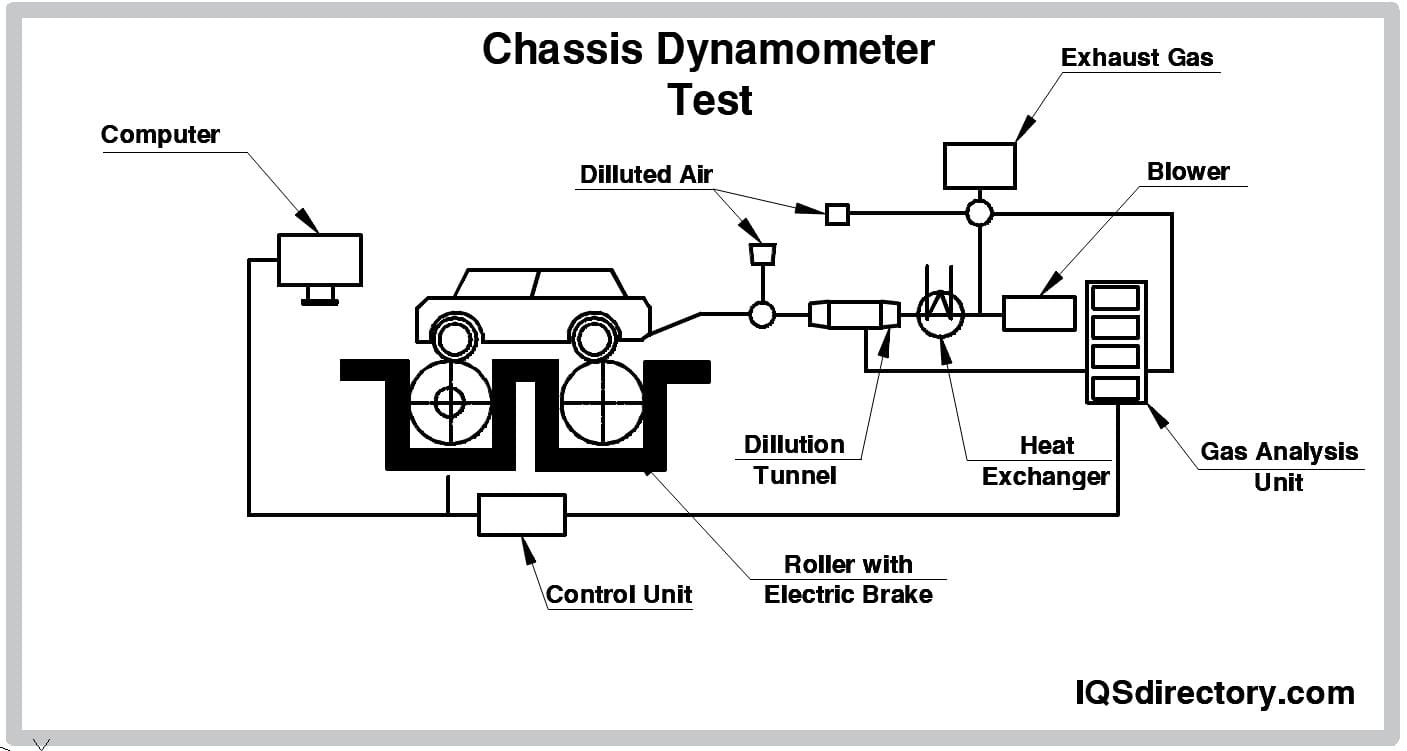 Motor testing using a dynamometer to measure the torque of a motor.
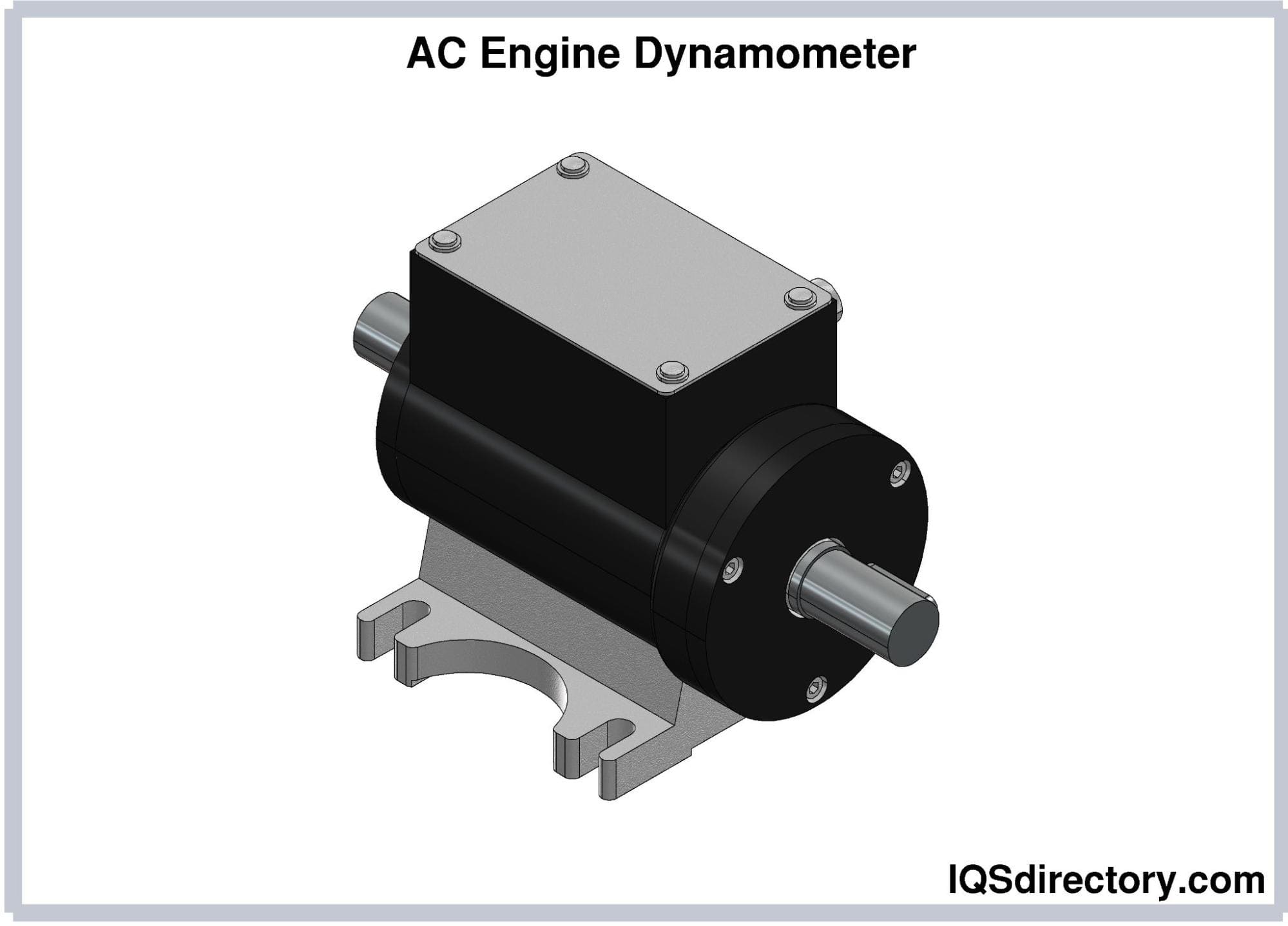 A dynamometer used to measure torque, force, speed, and power required to operate the drive of a machine or motor.
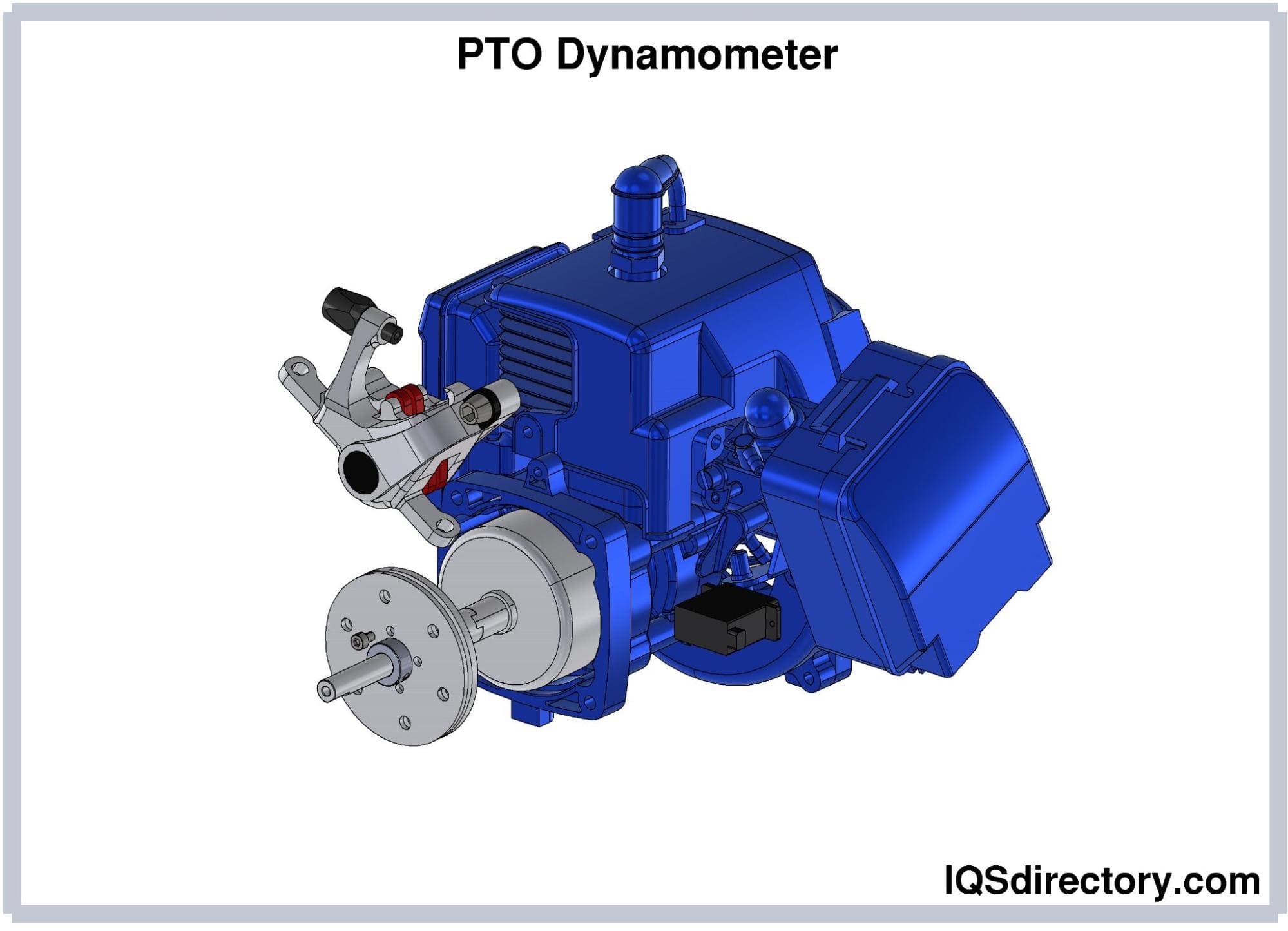 PTO testing is a series of tests performed by a dynamometer connected to an engine’s output shaft and tests speed, torque, power, and fuel consumption.
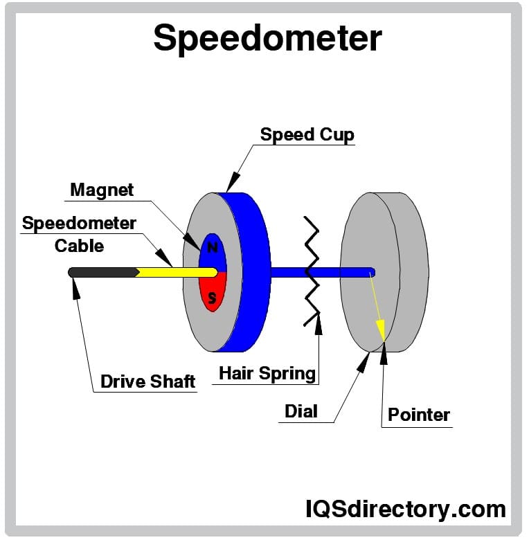 A speedometer, a form of dynamometer that uses electromagnetism which provides data.
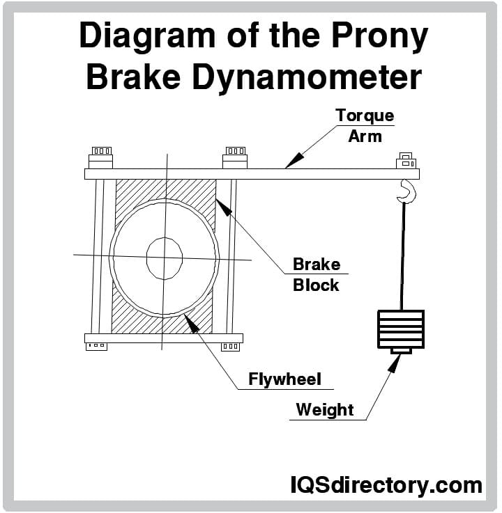 A Prony brake dynamometer is the simplest form of dynamometer that Prony developed, which is made up of brake blocks that press against a rotating wheel attached to the motor to measure braking power.
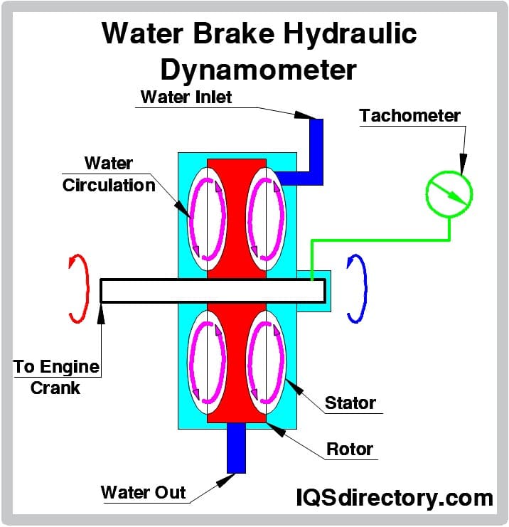 Water brake dynamometers are designed to work with high torque low speed diesel engines used in mining, marine, and naval applications.
Types of Dynamometers
Transmission Dynos
- Towing Dynamometers
- Act on a similar principle by creating a constant load on the vehicle towing the dyno. This is used to calculate appropriate load levels for the vehicles in question.
- Chassis Dynamometer
- Motor testing uses a test cell consisting of a one- or two-roller bed onto which the vehicle being tested is placed. The rollers provide the driving force to the wheels of the vehicle rather than using the torque of the motor as the prime mover. Computers are connected to the mechanical operations of both vehicle and test equipment, allowing for highly controlled, accurate dynamometer testing of a motor without removing it from the vehicle. Tractive forces between axles may be distributed evenly or not, depending on the information required through testing. Speed may be controlled by the varied application of force to the wheels, measuring static power at constant velocity.
- Chassis dynamometers measure an engine's torque output at the wheels of an automobile. The auto is placed on rollers, on which the tires turn, and the result is then measured. Some chassis dynamometers also work by attaching directly to the wheel hub and measuring its rotation. Chassis dynamometers may be fixed or portable units.
- Road Load Simulation Dynamometer
- Simulates road conditions, such as inertia and grade. Initial base readings, road parameters, are taken with the vehicle traveling on a simulated flat road without wind from any direction, and gear set in neutral. Braking times at varied intervals are taken. These parameters are entered into the workstation computer along with vehicle inertia. Specified alternate conditions are then applied. Because a simulated road cannot factor in aerodynamics, air drag must be calculated into the engine dyno and is facilitated through the use of increased brake force to the wheels of the test vehicle. Simulated changes in gradient are accomplished this way as well. As the computer reads the data from the tests, it can calculate the simulations into working results and recommendations for improving efficiency.
- Dynos can be configured to match the needs of the user. From small mechanic shops to houses of international industry, from torque specs to exhaust flow, dynamometer test equipment systems can be custom-designed to fit a space or a space can be designed to fit the dyno. A good dynamometer company will take into consideration the purpose of the testing, the availability of shop space, and the economic advantage to the customer to help design a workplace and system that functions safely and efficiently. It will provide the proper machinery and equipment to correspond with the user's needs and capabilities and offer technical support to ensure the client's success.
Power Absorption Dynos
- Hydraulic Dynamometers
- Similar to water brake dynamometers in principle. They use an impeller enclosed inside a casing filled with hydraulic fluid and coupled to the prime mover. Centrifugal forces revolve with the impeller as friction is generated through resistance against a torque arm attached to a balance weight. The friction is measured by a spring balance. Flow through the impeller is controlled by the use of sluice gates. Heat created through the friction is dissipated in the continuous flow of the fluid.
- Eddy Current Dynamometers
- Determine the torque of an engine by creating eddy currents by moving a conductor through a changing magnetic field.
- Eddy current dynamometers, developed in the 1930s, are a type of absorption dyno that consist of an electrically conductive, rotating core inside a magnetic field. They use electromagnets attached to the stator and a copper or steel rotor attached to the output shaft to place a load on an engine through the conduction of electricity. Rotation of the rotor creates eddy currents, due to magnetic flux in the stator, which can be measured by a moment arm. The developing eddy currents are smooth and can be controlled to match the torque of driving force. Eddy current dynos provide smooth operation with good control and accurate readings without limitations on the size of the engine being tested. Because of heat created by the friction, eddy current dynamometers must be externally cooled.
- Power Take Off Dynamometers
- Are used in industrial and agricultural sectors. They use an external drive, usually located in a truck or a tractor, to provide power to the attached machine. The PTO dynamometer uses an eddy current to measure torque. PTO dynamometers are measurement and diagnostic equipment used to test the performance of power take-off components in engines.
- Power Dynamometers
- Similar to an eddy current dyno, uses a fine magnetic powder in the air gap between the rotor and the electromagnets on the stator to create metal particula
- Inertia Dyno
- Uses an electric motor to turn a flywheel mass approximately equal to one-fourth the weight of the test vehicle. Once the flywheel achieves RPM equivalent to specified vehicular speed, braking forces are applied and measured. Inertia dynamometers are becoming the most widely used type of dynamometer in the torque-testing sectors of both the commercial and racing automobile industries because they provide real-world results. The inertia of the roller drums is measured to calculate torque, revealing the rate at which an engine can accelerate a known rotational inertia from one RPM to another.
- AC Dynamometer
- Driven by an electric motor using alternating current, as opposed to direct current. The AC control unit uses a transducer called a load cell to provide an electrical signal to a variable frequency drive at a magnitude proportional to the force being tested. The drive can be configured into a universal dynamometer which absorbs the power of the engine but can also drive the engine for measuring friction and pumping losses. They are typically more complex than other types of dynamometers, therefore more expensive, but their regenerative control units may be harnessed to collect and sell electricity back to the utility provider.
- Rope Brake Dynamometer
- Also measures braking power. Turns of rope are wound around a cylinder or rotating drum attached to the prime mover. One end of the rope is attached to a spring balance and the other end is attached to a loading device, which can be as simple as a hanging weight. Rope brake dynamometers are inexpensive but are not very accurate due to the coefficient of friction in the rope which changes with the buildup of heat when tension is applied.
Other Dynamometer Types
- Brake Dynamometers
- Measure horsepower at the engine's output shaft by applying variable load on the engine and evaluating its ability to maintain its speed as the braking force is applied.
- Brake Testers
- Used to test the effectiveness of a vehicle's braking system. As pressure is applied to the brakes, the force produced is measured, recorded, and displayed by the testing system.
- Dynos
- Machines that measure the torque of an engine.
- Engine Dynamometers
- Another sub-type of torque testing machines, which are hooked to the engine directly as opposed to the wheel chassis. Research and development departments at workshops and auto manufacturing plants use this style of testing, as the engine can be tested without being inside a vehicle.
- Hydraulic Dynamometers
- Machines that measure the power of an engine by using a cell filled with liquid to increase its load.
- Motor Testers
- Measure the performance of motors to ensure that they are efficient and safe. The equipment is automatic, performing a sequence of steps to determine whether the demonstrated capabilities of the motor are acceptable.
- Portable Dynamometers
- Used to measure the force, torque, or power. They are also used to determine how much torque or power can be used to operate a driven machine like a pump.
- Repair Grade Dynamometers
- Chassis devices used to simulate actual road driving conditions on a motor vehicle. Repair grade dynamometers consist of rollers, power absorbers, and inertia simulation, either mechanical or electrical.
- Torque Testers
- Function basically the same way as dynamometers do, but are designed to test the torque of smaller mechanical devices other than engines. Devices such as precision screwdrivers and wrenches need to have their torque tested to ensure quality function.
Dynamometer Accuracy
When it comes to precision in torque measurement, there is no match for dynamos. Whether you want to measure force, torque, or power output/input, dynamometers will provide the most accurate data. You can install these systems with any application, depending on your requirements. However, to attain the most accurate assessment, you will need to make sure that the devices have been installed correctly.
Testing with Dynamometers
To test the performance of an engine, test engineers need to thoroughly understand the dynamometer's operating instructions. A dynamometer controller is an electronic unit that enables engineers to control the load pressure on an engine. By gaining control over the control panel, you can measure the speed of and load on the engine. You can set the control panel to work for either Speed Control or Load Control.
For engine testing, various tests can be carried out using a good quality dynamometer or torque tester. When testing engine performance, make sure to perform the test with a wide-open throttle. You should also ensure that the test is being performed in Speed Control mode. During the initial stage of the test, the speed should be set at a low level to measure the engine speed and torque. Then, the speed level can be increased. After the increase, the performance measurement should be noted. This process should be repeated until the desired speed has been achieved or set.
During power or force measurement testing, it is important to provide adequate cooling to the engine. This practice helps to mitigate the problems caused by overheating. Cool air can be provided by fans and other cooling mechanisms. Some large industrial processes may need a cool air flow, flowing at 25 mph. To avoid hazards or inaccuracy in testing assessments, you should consider testing the temperature during the run of the machine.
Selecting the Proper Dynamometer
Dynamometers come in different types, each tailored to specific applications and motor requirements. Their design and functionality vary depending on the process they are used for. Some models are compact and handheld, ideal for engineers, medical professionals, and construction specialists, while larger units are built for industrial applications. Regardless of size or purpose, modern dynamometers feature a digital interface that provides precise measurements of force and torque.
Dynamometer Terms
- Ambient
- The temperature of the surrounding environment.
- Base Line
- A reference vibration reading taken when equipment is operating optimally, used for future testing and monitoring.
- Breakdown Torque
- Also called maximum torque or pull-out torque, it is the highest amount of torque an AC motor can generate when running at its rated voltage and frequency before experiencing a sudden speed drop.
- Chassis
- The structural framework of a vehicle, including the engine, suspension, wheels, and steering components, but excluding the outer body.
- Code Letter
- A designation found on AC motor nameplates indicating the locked rotor kilovolt amperes per horsepower at a specified frequency and voltage.
- Dynamometer
- A device used to measure power output by absorbing energy produced by an internal combustion engine.
- Dynometer
- An alternate spelling for dynamometer.
- Full Load Speed
- The rotational speed (RPM) of an engine or generator when running at its full torque capacity.
- Full Load Torque
- The required torque to produce the rated horsepower of an engine or generator at its full load speed.
- Horsepower (HP)
- A unit of measurement for work rate, where one horsepower equals approximately 550 foot-pounds per second or 746 watts.
- Inertia
- The tendency of an object in motion to maintain its velocity unless acted upon by an external force.
- Locked Rotor Torque
- The minimum torque an engine can generate when starting from a standstill, measured at all angular positions of the rotor while receiving its rated voltage and frequency.
- Output
- The total power generated, calculated as the product of available torque and rated RPM.
- Rotor
- The rotating component within a motor or engine.
- R.P.M. (Revolutions Per Minute)
- A unit used to measure rotational speed, determining power and torque.
- Throttle
- The mechanism that controls acceleration by regulating airflow into the engine.
- Torque
- A measurement of rotational force, typically expressed in foot-pounds.
- Transmission
-
A system of gears that transfers power from an engine to a vehicle’s drivetrain.
- Trending
- The process of tracking changes in measurement data over multiple intervals to identify performance variations.
- Velocity
- The rate at which an object changes position over time.
- Wide Open Throttle (WOT)
- The position of the accelerator pedal that allows maximum airflow into the engine's intake manifold, enabling full power output.

