Gears
Industrial gears are mechanical components with toothed edges that facilitate rotary motion, used to initiate or alter movement in machinery. They are designed to transmit or modify torque (rotational force), rotational speed, and direction within the devices or machines they are connected to.
In contrast to gears used in commercial and consumer products, industrial gears are typically built with robust construction and durable metal materials, allowing them to withstand demanding applications and heavy-duty usage.
Industrial Gears FAQ
What are industrial gears used for?
Industrial gears transmit torque, alter speed, and change the direction of rotary motion in machinery. They are essential in industries like automotive, aerospace, food processing, and material handling where precision and durability are critical.
What materials are industrial gears made from?
Industrial gears are commonly made from metals such as steel, stainless steel, brass, copper, and titanium for strength. In lighter-duty applications, durable plastics like nylon and polycarbonate are used for reduced weight and noise.
What is gear ratio and why is it important?
Gear ratio is the relationship between two interlocking gears, determined by their number of teeth. It controls how fast one gear turns relative to another, directly affecting speed, torque, and mechanical efficiency in industrial machinery.
How are industrial gears manufactured?
Gears are produced using methods like injection molding, powder metallurgy, forging, die casting, investment casting, sand casting, and increasingly 3D printing. Additional processes like hobbing, shaping, and heat treating improve performance and durability.
What industries rely most on industrial gears?
Automotive manufacturing, aerospace, oil and gas, mining, machining, food processing, textiles, and automation all rely on gears for transmitting motion and power. Gears are critical for machinery performance across these heavy-duty sectors.
How should industrial gears be maintained?
Regular inspections, proper lubrication with gear oils, dust and pollution control, and clear maintenance plans are essential for long gear life. Preventive care reduces wear, overheating, and downtime in demanding industrial environments.
What standards apply to industrial gears?
Industrial gears are often manufactured to ISO and AGMA standards, along with industry-specific requirements such as Mil-Specs, DIN, JIS, FDA, or EPA compliance. Meeting these standards ensures safety, reliability, and performance in specialized applications.
Applications of Industrial Gears
Industrial gears serve two primary purposes: they transfer rotational motion and enable changes in rotational speed and torque.
These gears are integral to a wide range of industries, including automotive manufacturing, aerospace and aviation, machining, material handling, food processing, textile manufacturing, oil and gas, and automation. Gears are crucial for the operation of equipment and products across these sectors and beyond.
For example, bevel gears, spur gears, and other gear types are essential in vehicles, enabling the transfer of rotational motion from the engine to the vehicle’s moving parts. They are particularly vital in automotive transmission systems. Additionally, gears are relied upon in applications such as clocks, bicycles, heavy mining machinery, and oil rig equipment for the transmission of motion.
History of Industrial Gears
Gears have their origins in China as early as the 4th Century B.C., with the earliest known gears in Europe emerging from Greece between 150 and 100 B.C.
The first use of differential gears is believed to be in a south-pointing chariot, created by the mechanical engineer Ma Jun in the second century A.D. Gears were also incorporated into mechanical clocks built in China around 725 A.D. Meanwhile, the worm gear was developed on the Indian subcontinent during the 13th or 14th century.
Throughout the centuries, gears have evolved, becoming more advanced and varied. Today, industrial gears are incredibly versatile and play a critical role in a wide range of applications.
Industrial Gear Design and Customization
The key component of industrial gears is their teeth, or cut cogs, which mesh with the teeth of another gear. These teeth are typically part of a "gear wheel," a toothed wheel that facilitates the gear's operation.
Manufacturers often create gears using net shape molding, a technique designed to produce parts that closely resemble their final form, minimizing the need for surface finishing. The processes involved in creating semi-finished parts are referred to as blanking operations. These include techniques such as injection molding, powder metallurgy, die casting, investment casting, and sand casting. Gears can also be made using forging methods and, increasingly, 3D printing.
Once produced, the part is called a gear blank. Gear blanks are often sent for further machining. While gears made through injection molding and die casting typically don’t need additional finishing, gears created using other methods often do. For example, powdered metal gears require sintering, while sand castings and investment castings usually need gear cutting. Gear cutting techniques include gear hobbing, shaping, broaching, and milling.
To increase durability and resist wear, manufacturers often strengthen gears through processes like heat treating and quench pressing.
Gears can be made from various materials, including metals and hard plastics. Wear-resistant plastics such as nylon and polycarbonate are ideal for applications requiring low weight. In demanding settings like automotive transmissions, gears are typically made from hard metals, including stainless steel, steel, brass, copper, and titanium.
Two key considerations in gear design are gear speed and performance, which are influenced by gear shape and size. When interlocking gears differ in size, the smaller gear turns faster than the larger one. This relationship is known as "speed ratio" or "gear ratio." For example, if one gear has 40 teeth and the other has 20, the gear ratio would be 2:1.
Another important factor in gear design is diametral pitch, which determines the gear’s movement speed within a machine. Diametral pitch refers to the number of gear teeth per inch of its pitch diameter. To calculate this, divide the number of teeth by the pitch diameter, which is measured by the pitch circle—the imaginary circle that connects the points where interlocking gears meet. If the gear system is designed correctly, the pitch circles of the gears will be tangent to each other wherever the gears mesh.
Gear applications are versatile and customizable, offering numerous configurations to achieve specific goals, such as increasing or decreasing speed, transmitting power, or reducing the force needed to perform a task. Manufacturers can create customized gear assemblies, such as industrial gearboxes, to suit complex applications. Gearboxes are especially useful for intricate tasks, and whether large or small, gears can be made to meet your exact requirements—ranging from 20-foot diameter industrial gears to small gears.
Features of Industrial Gears
A gear's number of teeth and its gear ratio are crucial in determining how the gear functions, its speed, and its role within a larger gear assembly. These factors not only influence the gear’s durability and strength but also determine how quickly it can engage. Specifically, when gears of different sizes mesh, they can either increase or decrease a shaft’s rotational speed. Furthermore, interlocking gears with unequal diameters can alter rotational speed and torque.
Gears work together as a system. When one gear turns, the interlocking gear turns as well, thanks to the teeth meshing. Gear motion can be initiated in several ways—most commonly, by applying physical force, as in the case of riding a bike, or mechanical force from a machine.
There are various gear accessories available, including handwheels, lug drives, miter boxes, and stem nuts. To determine which accessories would best suit your needs, it's a good idea to consult with your supplier about your specific application.
Advantages of Industrial Gears
The primary advantage of industrial gears lies in their precise tooth ratio. This ratio enables industrial gears to operate with far more accuracy compared to alternative drives, like the traction drive.
Additionally, gears have the benefit of fewer components. Fewer parts mean fewer opportunities for malfunctions, reduced maintenance needs, easier cleaning, and, ultimately, a longer lifespan.
Proper Care of Industrial Gears
To ensure that your industrial gears are performing at their best and meeting production demands efficiently, it’s essential to maintain them properly. Even the most advanced industrial gears need regular upkeep to function optimally. Below are some tips to keep your gears in top condition.
- Prepare Maintenance Plan
- Every maintenance routine should be clearly outlined and followed. Work with your process engineers to develop a comprehensive plan for your machinery's care and upkeep. This plan should include all necessary cleaning and maintenance tasks and serve as a daily checklist for your team. Be sure to outline the specific duties your engineers and maintenance staff need to perform to ensure the smooth operation of your industrial machinery.
- On-Site Pollution and Dust Management
- It’s critical to have effective dust and pollution control measures in place at your site. A lack of a pollution management system can negatively impact the performance of your machines and affect product quality. Dust and pollutants can disrupt the smooth rotation of gears, leading to inefficiency and additional production costs. Many machines, including production machinery, power generators, and air conditioning systems, generate particulates that can spread throughout the facility if proper pollution control measures aren’t in place.
- Keep Support Tools Nearby
- Efficiency is key, so your engineers should work in a well-organized manner with all the necessary tools on hand. Ensure that tool kits, testing devices, and safety equipment are easily accessible near the machinery. Tool belts that can be worn during maintenance tasks are an excellent choice to keep essential tools within reach. Additionally, verify that your engineers understand the requirements for testing and have a strong working knowledge of the machines’ gear systems.
- Visual Inspection Before Every Production Cycle
- A quick inspection before starting each production cycle can save time and resources. Open the gearbox and check the condition of all visible components. Make sure to document any visible settings, or use an HD camera to capture them for reference. This step helps ensure that your machines are operating correctly and that no issues are present before production begins.
- Inspect Heat Sources
- To improve the performance and longevity of your gears, use industrial gear oils for lubrication. Gear oils help protect gears against heat, vibration, friction, and corrosion. Without proper lubrication, your gear systems can overheat, corrode, and break down more quickly. Choose the right lubricant based on the specific requirements of your application, ensuring it offers the necessary strength, heat resistance, and corrosion protection to maintain the efficiency of your industrial gears.
Industrial Gear Standards and Compliance
Generally, your manufacturers should adhere to the standard guidelines established by the ISO (International Standards Organization) and AGMA (American Gear Manufacturers Association).
Additionally, they should follow any relevant standards specific to your industry, region, or country. These may include Mil-Specs, FDA standards, EPA standards, DIN standards, and JIS standards. To ensure your gears meet all the necessary requirements for your application, it’s important to discuss your specifications thoroughly with your gear supplier.
Points to Consider When Selecting Industrial Gears
Industrial gears come in many different varieties, and they can first be divided into two main categories: internal gears and external gears. Internal gears have teeth located on the inner surface of the wheel, while external gears have teeth on the outer surface. It’s important to note that a bevel gear is only classified as an internal gear if its pitch angle exceeds 90 degrees.
Within these two categories, there are many different types of gears.
Choosing the right gears for your needs is a crucial decision, as they play a key role in the performance of your machinery. When selecting gears, consider factors such as the operating environment, required speed, torque, intended frequency of use, and industry-specific standards.
To ensure you select the right gears, it’s best to work with a reputable gear manufacturer. The ideal manufacturer for you is one that demonstrates genuine commitment to understanding your needs and providing effective solutions. Not sure where to start? Don’t worry! We’ve listed several reputable gear manufacturers above. Check out their websites and reach out to one or more of them with your questions to find the right fit for you.
Gear Images, Diagrams and Visual Concepts
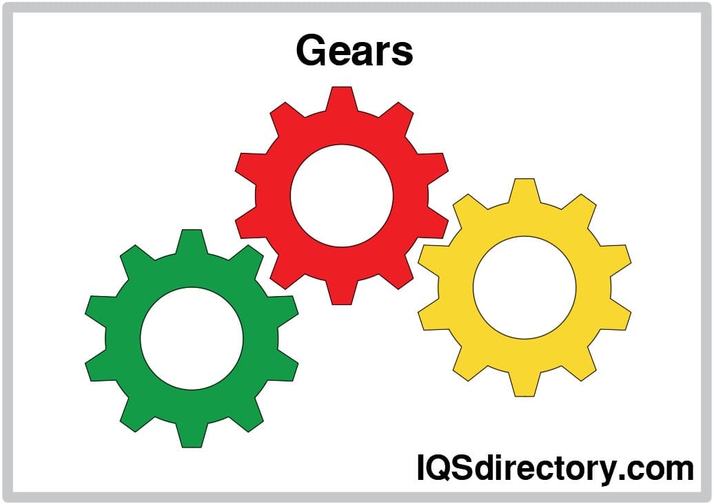 Gears allow for the change in direction, speed and torque of the power device.
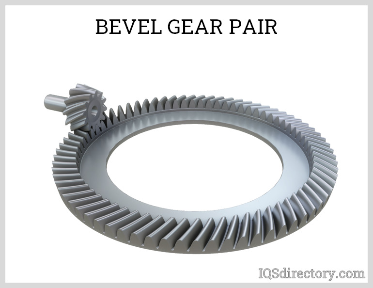 Bevel gear, a toothed rotating machine element used to transfer mechanical energy or shaft power between shafts that are intersecting, either perpendicular or an angle.
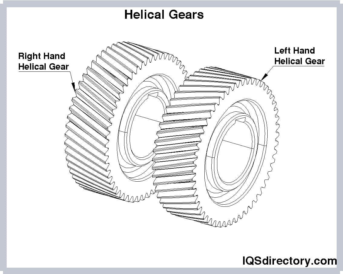 The purpose of helical gears are to provide power transmission devices is to enhance torque and decrease speed between rotating shafts.
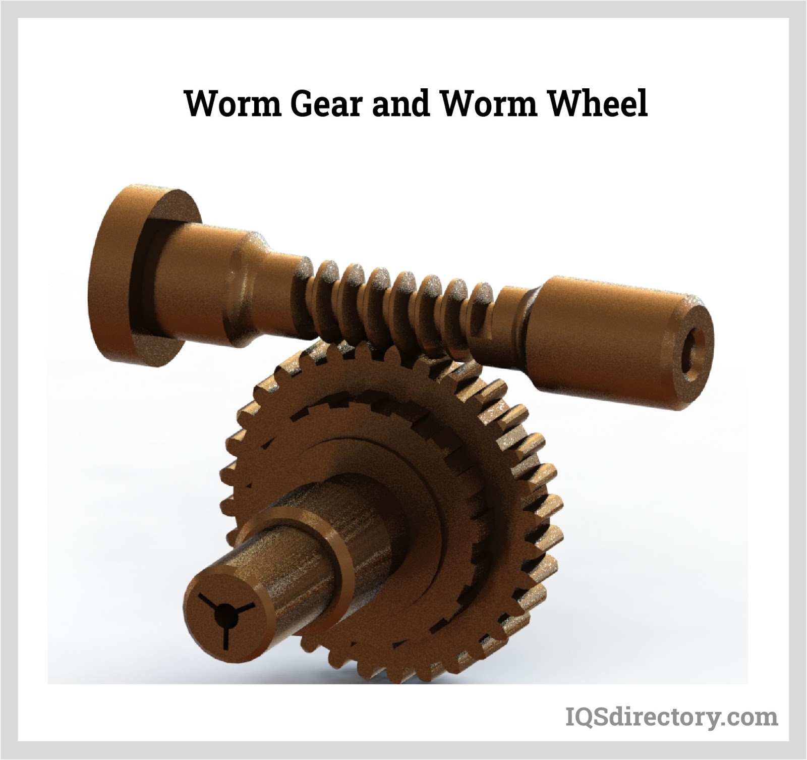 A staggered shaft gear that creates motion between shafts using threads that are cut into a cylindrical bar to provide speed reduction.
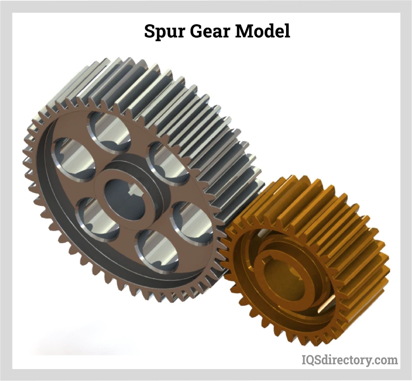 A cylindrical toothed gear with teeth that are parallel to the shaft and to transfer mechanical motion and control speed, power, and torque between the shafts.
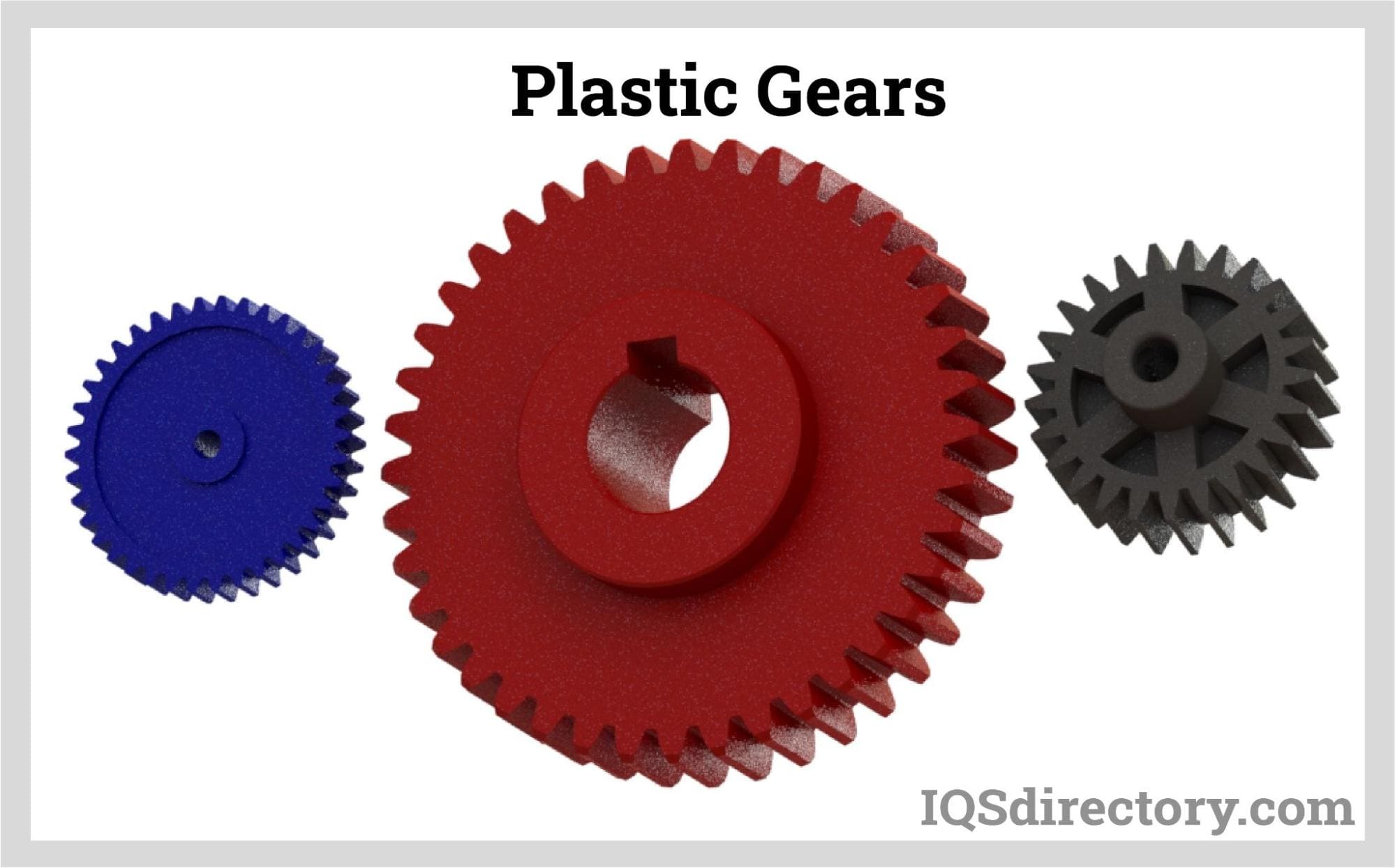 Plastic gear is a toothed wheel consisting of engineering plastic materials which works alter the relation between the speed of an engine and the speed of the driven parts.
Notable Gear Types
- Bevel Gears
- Operate on intersecting axes, typically at a 90-degree angle, to transmit motion around corners. These gears feature teeth arranged on intersecting, coplanar shafts, known as a bevel gearing system. Bevel gears are used in various applications, and their tooth thickness and height should be selected according to the specific application requirements.
- Differential Gears
- Link two shafts through a covering, ensuring that the total rotational angle of the shafts equals the rotational angle of the covering.
- Gear Manufacturers
- Companies that produce torque transmission equipment, specializing in the design and manufacturing of various types of gears.
- Helical Gears
- These gears have angled teeth that create thrust load when meshed. Common in automotive transmissions, their teeth are inclined toward the shaft's axis and arranged in a helical pattern. Known for their smooth operation, they can bear both radial and thrust loads. They are quieter and more efficient than spur gears, making them ideal for automotive applications.
- Gear Rack
- A straight line of equally spaced teeth used in various applications to convert rotational motion into linear motion.
- Herringbone Gears
- Used to transmit power and motion between parallel, non-intersecting axes, with each tooth forming two opposite helices. These gears may or may not have a central groove.
- Hypoid Gears
- Similar to bevel gears but work on non-intersecting axes. They offer smoother and quieter operation, particularly in automotive applications.
- Industrial Gears
- Round mechanical components with teeth around the circumference, designed to interconnect with corresponding gear wheels or parts to transfer motion, increase or decrease rotational speed, and torque.
- Metric Gears
- Defined by the millimeter length of the pitch circle diameter per tooth, these gears are designed according to the metric system for international applications.
- Miter Gears
- A type of bevel gear with equal numbers of teeth and axes typically positioned at right angles. Miter gears allow for the transmission of rotational motion at a set speed.
- Planetary Gears
- Comprising a central "sun" gear surrounded by multiple "planet" gears, planetary gears operate inside a larger internal gear to create complex gear ratios. They provide a compact design for high torque applications, commonly used in drivetrains and complex machinery.
- Plastic Gears
- Primarily made of plastic materials, sometimes combined with metal components, these gears are lightweight, cost-effective, and commonly found in applications requiring non-metallic components.
- Pinion Gears
- Small round gears typically used as the driving gear in a gear set, such as in a rack and pinion mechanism.
- Rear End Gears
- Bevel gears arranged in an epicyclic configuration to transmit torque and rotation through multiple shafts, typically used in rear axle systems of vehicles.
- Spline Gears
- Gears featuring a series of ridges on a driveshaft that synchronize the rotational speed of the corresponding gear, providing smooth transmission of motion.
- Sprockets
- Gears with teeth that mesh with chains, commonly used in applications like bicycles and tank treads. They serve as pulleys for power transmission systems, providing a non-slip connection.
- Spur Gears
- Cylinder-shaped gears with straight, parallel teeth that work on parallel axes. These are the most common and simple type of industrial gear, known for their straightforward design and efficient performance.
- Straight Bevel Gears
- Bevel gears with straight teeth that radiate from a center point, used to transfer motion between intersecting shafts.
- Spiral Bevel Gears
- Similar to helical gears, spiral bevel gears have curved teeth that provide higher load capacity compared to straight bevel gears. Their design allows for smoother and quieter operation under heavy loads.
- Worm Gears
- Gears with a curved, recessed throat that meshes with the worm gear teeth. Often made from materials like bronze or steel, worm gears are used to achieve high torque, low-speed gear ratios.
- Zero Bevel Gears
- These gears resemble straight bevel gears but have curved teeth that are not angled. They serve as an intermediate type between spiral and straight bevel gears, providing a balance of performance in specific applications.
Gear Terms
- Backlash
- The gap between the width of a tooth space and the thickness of the engaging tooth on the pitch circles of industrial gears.
- Bore
- The diameter of the central hole in an industrial gear.
- Bull
- The larger gear in a set of industrial gears.
- Center Distance (CD)
- The shortest distance between the axes of non-intersecting, mating industrial gears.
- Coupling Sprockets
- Used to connect two non-continuous shaft ends of industrial gears.
- Dedendum (DED)
- The radial or perpendicular distance between the bottom of the gullet and the pitch circle on industrial gears.
- Gullet
- The space between the teeth of industrial gears.
- Hob
- A cutting tool used to create teeth in industrial gears using a hobbing machine.
- Hub
- An extension on the side of industrial gears that provides the necessary width to mount the gear onto a shaft.
- Hub Style
- The design of the hubs on industrial gears: Type 'A' indicates no hub; Type 'B' indicates a hub on one side; Type 'C' indicates a hub on both sides.
- Module (MOD)
- The ratio of the pitch diameter to the number of teeth on an industrial gear, measured in millimeters.
- Mounting Distance (MD)
- The distance from the intersection of the axes to the location surface of industrial gears.
- Pinion
- The smaller gear in a set of industrial gears.
- Pitch
- The size of the teeth on industrial gears.
- Rack
- A steel bar with teeth on one side that allows a pinion to be driven across. It is also a spur gear with an unlimited pitch diameter.
- Ratio
- The relationship between the size of one industrial gear and another, measured from the center of the gears to where their teeth or edges meet.
- Teeth
- The protrusions or indentations on the edges of industrial gears that interlock with other gear parts. The teeth prevent slippage and ensure the gears function consistently and efficiently.