Hydraulic Valves
Hydraulic valves regulate and guide the flow of fluid within a system of pipes, hoses, or cylinders, transforming fluid pressure into mechanical energy. This energy is transferred throughout the hydraulic system via accumulators, pumps, and actuators to power various types of equipment across countless applications. These valves typically operate within a closed-loop system that includes a reservoir, allowing fluid to release its force before cycling back to the reservoir for ongoing operation.
A Brief History of Hydraulic Development
-
Ancient Hydraulics
In Ancient Greece, Aristotle observed that water behaves as a continuum. A century later, Archimedes introduced the principle of displacement, explaining that a body submerged in water is buoyed by a force equal to the water it displaces, and identified the importance of pressure gradients in fluid flow. At the dawn of the 16th century, Leonardo da Vinci developed the first known mathematical formula for flow and designed an early closed-loop control system to regulate water flow to a wheel.
These foundational ideas contributed significantly to the development of both hydrostatics (the study of fluids at rest) and hydrodynamics (fluids in motion), laying the groundwork for what would eventually become hydraulic technology. In 1648, Blaise Pascal introduced the Hydrostatic Transmission Theory, asserting that pressure applied to a confined fluid is transmitted equally in all directions. Known today as Pascal’s Law, this principle remains a cornerstone of modern hydraulics.
In 1795, Joseph Bramah patented the first hydraulic press, a design that has endured in various forms to this day. Advancements in hydraulic science followed with contributions from great thinkers like Robert Boyle, Sir Isaac Newton, Daniel Bernoulli, and Leonhard Euler, all of whom expanded the theoretical framework supporting hydraulic systems.
Hydraulics in the 1900s
By 1907, Harvey Williams and Reynolds Janney had developed the first axial piston devices, capable of functioning as both pumps and motors. These devices required a suitable lubricant, and water proved inadequate, prompting the shift to oil-based hydraulic systems, which quickly eclipsed water hydraulics in industrial use.
However, in 1956, a tragic mining accident in Belgium—triggered by the rupture of a hydraulic oil line and a severed electrical cable—resulted in a fire that claimed 262 lives. In response, legislation was passed mandating the use of water-based hydraulics in certain industrial and underground applications for safety. Today, both water and oil hydraulic systems are in active use, chosen according to the specific requirements of safety, power, and environment.
Making a Hydraulic Valve
Most hydraulic valves are constructed from iron, brass, steel, or stainless steel, chosen for their strength, durability, and resistance to corrosion under pressure. In smaller or low-pressure systems, plastics may also be used. The valve seat—the outer housing that contains the mechanism—and the body—the internal component responsible for opening and closing the flow channel—are typically manufactured through casting, die forging, or machining, depending on the application and material. To operate the valve, an external control mechanism such as a wheel or lever is integrated with the body, allowing precise manual regulation of fluid flow.
How Hydraulic Valves Work
-
Hydraulic Valve Stations
Hydraulic valves typically operate in two primary positions: open and closed. When closed, they block fluid flow entirely; when open, they allow fluid to pass freely. Within fluid control systems, hydraulic valves offer a reliable method for regulating pressure and fluid levels. The simplest example involves two equal-sized pistons within two cylinders connected by a fluid-filled pipe. Applying force to one piston causes the other to rise, as the fluid—being incompressible—can only be displaced, not compressed. Because of this property, the connecting pipe may assume any shape or length. As long as it remains full and free of air bubbles, pressure applied at one end will transmit nearly equally to the other.
Hydraulic Power Transmission and Master-Slave Systems
This principle makes hydraulic power transmission highly effective. Systems can divide power through manifolds and secondary (slave) cylinders controlled by a master cylinder. A common example is an automobile braking system, where a single pedal simultaneously activates all four brakes.
Pistons and Hydraulic Force Multiplication
The pressure at the output end of a hydraulic valve can be increased or reduced by varying piston and cylinder sizes—a principle known as hydraulic multiplication or division. For instance, a two-inch diameter piston traveling nine inches can displace fluid to lift another two-inch piston the same distance. But if the second piston is six inches in diameter, with nine times the surface area, it will rise only one inch but exert nine times the force—900 pounds from an initial 100. Engineers can use formulas to determine the optimal piston sizes and valve arrangements for specific applications.
Flow Rate Management and Valve Functions
Some valves are designed to shut off flow when it exceeds safe levels, while others communicate with neighboring valves to regulate balance across a system. These functions help safeguard hydraulic systems from damaging pressure spikes. In more advanced setups, solenoid-operated valves use electric current to generate a magnetic field that actuates a plunger, controlling the valve’s open or closed position.
Check valves allow fluid to enter through an inlet and exit through an outlet, preventing backflow. Directional control valves permit multi-directional flow by shifting internal components to align with different ports or lines. Control valves maintain proper pressure and fluid volume, while relief valves protect systems from overpressure by redirecting excess fluid into an auxiliary passage.
Overall Function of Hydraulic Valves
Ultimately, hydraulic valves serve to manage and protect fluid systems—ensuring safe and efficient passage of fluids, preserving mechanical components, and maintaining system stability.
Hydraulic Valves Images, Diagrams and Visual Concepts
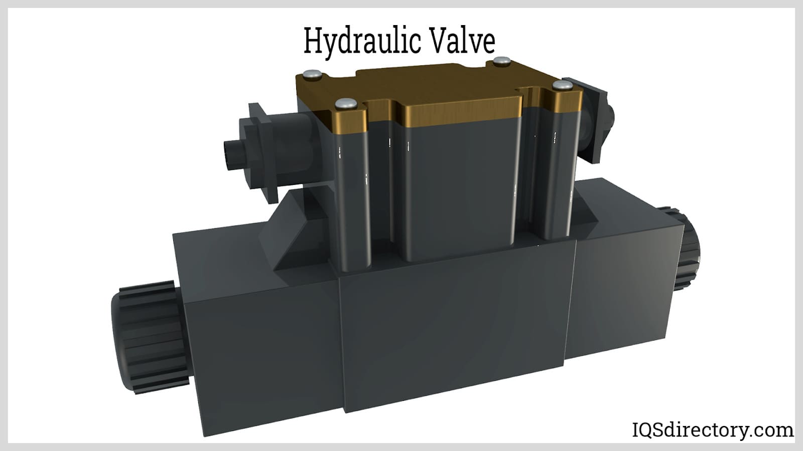 A hydraulic valve, a mechanical device that regulates the flow of the hydraulic fluid.
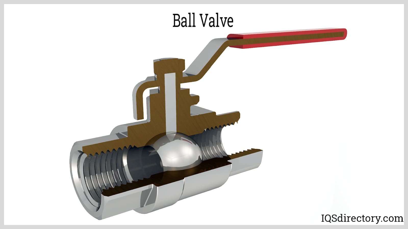 Ball valve is a shut-off valve that allows, obstructs, and controls the flow of hydraulic fluid.
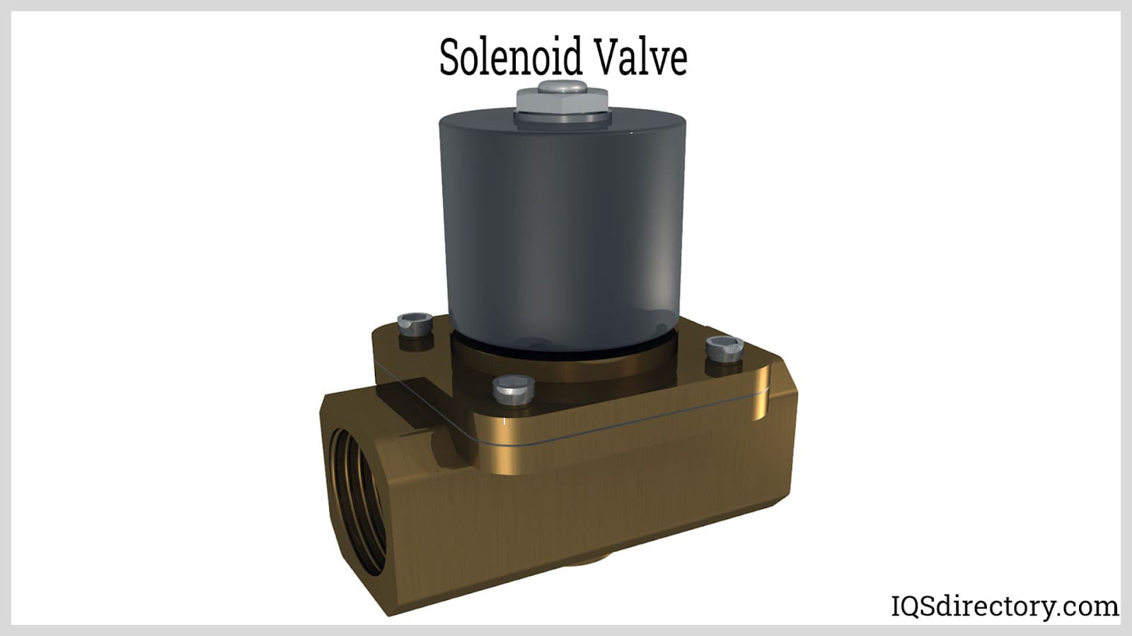 Solenoid controlled directional valve are used in hydraulic systems for opening, closing, or changing the direction of the flow of the liquid.
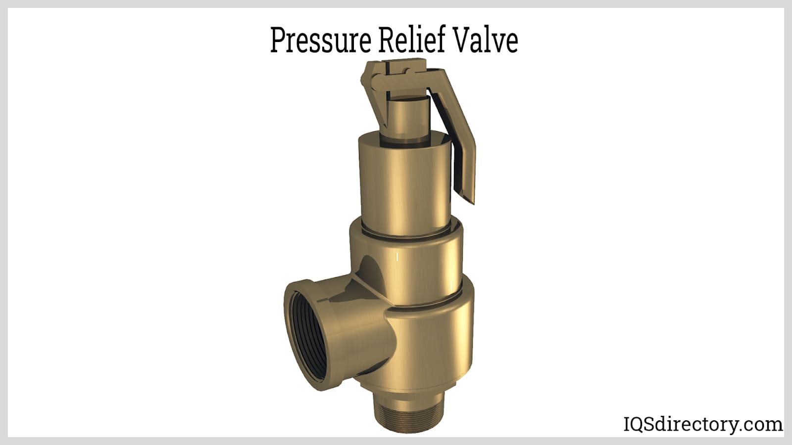 Pressure-control valves regulate the fluid pressure in a hydraulic system by making sure the system pressure does not exceed a certain set point.
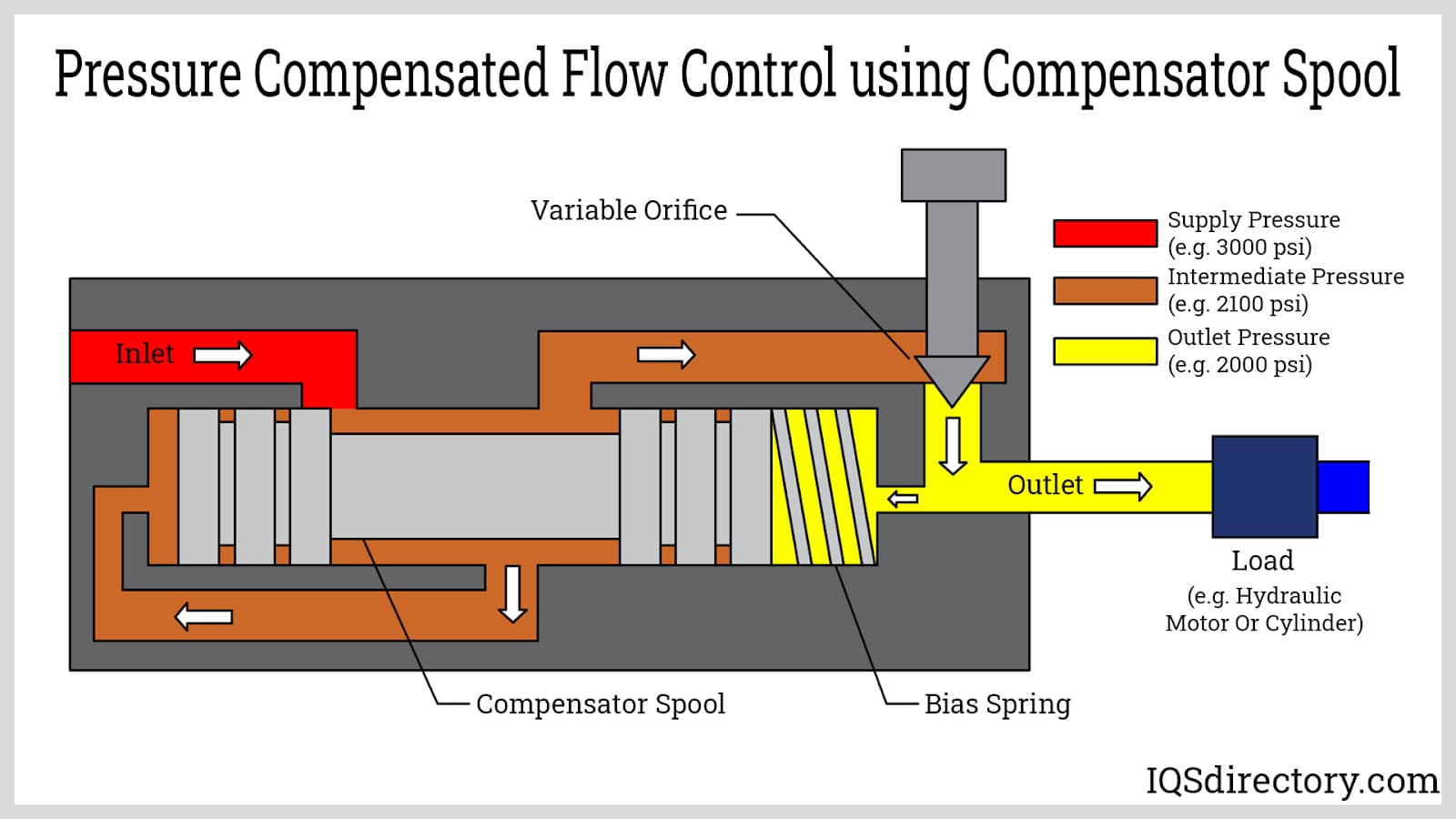 Pressure compensated flow control valves are designed to maintain a constant volumetric flow rate despite any pressure drops across the valve.
Types of Hydraulic Valves
Ball Valves
Parts that control fluid flow and pressure using a spherical element to create a seal. They are ideal for high-pressure applications requiring fast shutoff.
Control Valves
Devices that manage the flow and pressure of hydraulic fluid. Types include check, cartridge, directional, relief, safety, shut-off, and solenoid valves, each offered in various sizes and pressure ratings.
Conventional Safety Relief (CSRV)
A spring-loaded pressure relief valve whose performance is directly influenced by changes in back pressure.
Directional Control Valves
Valves that guide hydraulic fluid to specific points within a system. Common in farm machinery and hydraulic tools.
Electric Hydraulic Valve
Valves that operate based on electric signals, which trigger fluid flow and pressure control.
Float Valves
Mechanically operated by a float, these valves open or close automatically in response to changes in liquid level.
Gate Valves
Linear motion valves that use a flat closure element to provide shutoff with minimal pressure loss when fully open.
Globe Valves
Multi-turn valves with a closing mechanism that moves perpendicular to the seat, suited for throttling and flow control.
Hydraulic Valves
General term for components controlling hydraulic fluid flow and pressure. Major parts include the casing, bonnet, seat, and disc.
Manifold Devices
Components that control fluid flow between parts in a hydraulic system, allowing monitoring and redirection between pump and actuators.
Needle Valves
Valves with narrow ports and threaded plungers for precise, low-flow regulation, often used in calibration applications.
Pressure Safety Valves (PSV)
Valves that quickly open or close based on inlet pressure, used exclusively for safety.
Pressure Relief Valves (PRV)
Valves that reopen once pressure normalizes, preventing further fluid flow under unsafe conditions.
Spool Valve
Also called a directional control valve, this component switches hydraulic flow paths to direct power. The spool’s position determines push or pull force direction.
Proportional Valve (P Valve)
A regulator that adjusts output pressure in systems with multiple lines, commonly used in automotive brake systems to reduce rear brake pressure.
Solenoid Valve (S Valve)
An electromechanical valve operated by current-induced magnetic fields, controlling flow through either direct or pilot operation.
Hydraulic Cartridge Valves
Threaded inserts—also known as logic or 2/2 valves—used in manifolds to regulate pressure, direction, or flow rate.
Check Valves
Two-port directional valves that only allow flow in one direction, closing under backpressure to prevent return flow.
Relief Valves
Safety valves designed to discharge fluid when pressure exceeds safe limits, commonly used to return fluid to a reservoir or vent steam.
Position Valves
Also known as 3-way valves, they contain two valves in one body and are used to pilot control other hydraulic valves.
Safety Relief Valves (SRV)
A type of relief valve characterized by rapid response and operation that scales proportionally with pressure increases.
Uses for Hydraulic Valves
Hydraulic valves are essential components in automotive systems, where they actuate brakes, control clutches and gear shifts, and support engine lubrication and air conditioning systems. Hydraulic cylinders are commonly used in car jacks to provide lift, while rescue tools like the Jaws of Life rely on hydraulic piston rods to cut, spread, push, or pull apart vehicle structures during emergency operations.
In heavy equipment, hydraulic valves manage thousands of pounds per square inch of pressure, enabling precise control over machinery functions such as dump truck bed movement, backhoe swing arms, grader blade adjustments, and the operation of track drives, conveyors, scissor lifts, and plastics manufacturing.
Hydraulic control valves are also key to high-tech and high-precision systems, from driving crane booms that lift railroad cars to guiding nanobots performing delicate microsurgery. They power the core of industrial automation and robotics, enabling tasks with unmatched force and accuracy. Without hydraulic valves, the functionality of amusement parks, drawbridges, and countless other systems would come to a halt, severely impacting multiple industries.
Hydraulics In Motion
One of the most straightforward examples of hydraulic machinery is the log splitter, powered by a four-stroke gas engine that drives an oil pump. This pump sends hydraulic fluid into a spool valve, which then channels the pressurized oil into a hydraulic ram. As the spool valve redirects fluid with amplified force, the ram—equipped with a splitting wedge—extends forward to push through a log when the operator engages the control lever. The hydraulic oil used in this process is stored in a reservoir, often fitted with a filter to ensure the fluid remains clean and free from contaminants.
The gear pump is the most common type of pump found in hydraulic systems. As a positive displacement pump, it efficiently moves high-viscosity fluids in a continuous stream. Inside the pump housing, two intermeshed spur gears—one powered by a motor, the other acting as an idler—rotate to create suction on the intake side. This draws hydraulic fluid into the cavity and propels it to the outlet. The tight tolerances between the gears minimize internal leakage and maintain directional flow integrity.
The hydraulic ram in a log splitter functions as a piston rod, driven by the fluid routed through the spool valve. As pressure builds against the ram, it steadily drives the wedge into the wood until it splits. When the operator releases the lever, the fluid is redirected back to the accumulator, resetting the system for the next cycle.
In larger hydraulic systems, such as those in heavy equipment, a network of pumps and rams connected by hydraulic lines works in unison to perform demanding tasks like lifting, digging, or hauling. The same hydraulic principles, when miniaturized, are capable of powering tools used in high-precision fields such as neurosurgery or ophthalmic procedures. In complex, multi-component systems, hydraulic valves can be governed by computer systems to ensure accuracy, repeatability, and full automation.
Hydraulic Maintenance and Safety
Wear gloves and safety glasses. Hydraulic fluids frequently contain chemicals that can irritate or damage the skin and eyes. Even more dangerous, a pinhole leak can spray fluid at extremely high pressure, potentially injecting oil into the skin. Ingesting hydraulic fluid, even accidentally, can lead to serious health consequences.
Monitor system temperatures. Many hydraulic fluids are flammable, making it critical to be aware of temperature thresholds and to avoid conditions that might cause ignition.
Clean up spills immediately. Hydraulic fluid is an effective lubricant—not just for machinery, but also for floors. Spills left unaddressed pose serious slip hazards in addition to equipment concerns.
Be mindful of environmental impact. Conventional hydraulic oils are not eco-friendly. If biodegradable or non-toxic alternatives are not feasible for your application, be sure to handle and dispose of fluids in accordance with environmental best practices.
Trust qualified professionals. Certified technicians can verify that machines are operating safely and efficiently. They can identify existing issues, provide maintenance insights, and help prevent costly failures down the line.
Hydraulic Valve Terms
-
Accumulator
A container that stores fluid under pressure and is used to absorb hydraulic shock.
Backpressure
The pressure exerted on the downstream side of a valve seat.
Bonnet
A removable outer component of a valve that allows for assembly and maintenance; sometimes considered part of the valve body.
Bleed
A small, controlled release of fluid from a pressurized system.
Cavitation
The formation of vapor cavities in a liquid when gas enters the stream and the pressure drops below the vapor pressure.
Cracking Pressure
The pressure point at which a valve begins to allow flow before reaching the full set pressure.
Cylinder
A device that converts hydraulic energy into mechanical motion and force.
Differential Set Pressure
The difference between the set pressure and a consistent superimposed backpressure.
Disc
The sealing element—often an O-ring or wedge—that closes the valve against the seat.
Full Flow
A system condition in which the maximum volume of fluid is permitted to move through the flow passage.
Flow Rate
The measured volume, mass, or weight of fluid passing through a system, typically regulated by valves.
Gear Boxes
Mechanical aids used to facilitate the operation of larger valves, such as ball valves, by reducing manual effort.
Hydraulic Actuator
A device mounted to the valve stem that uses hydraulic energy to initiate valve opening and closing.
Hydraulics
The branch of science concerned with the motion and behavior of fluids.
Meter
An instrument that measures pressure levels and fluid volume in a hydraulic system.
Overpressure
The amount by which system pressure exceeds the valve's set pressure during fluid discharge.
Pre-Charge
The residual pressure present in a hydraulic actuator before hydraulic oil is introduced.
Reduced Bore
Indicates that the valve’s internal diameter is smaller than that of the pipeline it connects to.
Seal
A device that prevents fluid leakage or contamination from entering a system.
Seat
The fixed surface on which a valve closes or presses to create a seal.
Set Pressure
The inlet pressure at which a valve is configured to open, hold, or regulate fluid flow.
Solenoid
A coil of wire that generates a magnetic field when energized, often used to actuate valves.
Superimposed Backpressure
The static pressure at the outlet of a relief device caused by the discharge system, present before the device operates; may be constant or variable.
Static Water Pressure
The measured water pressure in a system when there is no flow.
Viscosity
A measure of a fluid’s resistance to flow, defined by its internal friction or shear strength under specific conditions.

