Speed Reducers
Speed reducers are mechanical devices designed to regulate output speed, serving more than a singular function. Primarily, they perform two essential roles. First, they decrease the input speed from the power source, adjusting it to the desired output speed. Second, they amplify the output torque, which represents the angular force applied to rotate an object. By incorporating speed reducers, the output torque is significantly multiplied compared to the input power source, enhancing its effectiveness and making it suitable for a wide range of applications.
The History of Speed Reducers
Speed Reducers in the 21st Century
-
Speed Reducers Before the 20th Century
The earliest known mention of a speed reducer-like mechanism appears in the works of Ismail al-Jazari, a Muslim polymath who described gearbox-like arrangements in The Book of Knowledge of Ingenious Mechanical Devices, written around 1206 AD. Despite his detailed accounts, his innovations were not widely implemented, and the development of modern speed reducers did not take shape until the 19th and 20th centuries.
In 1817, the British engineering and manufacturing company Watt & Boulton Engine introduced a gearbox design incorporating two gears and a governor to regulate rotational speed. By 1881, the French company de Dion-Bouton had begun producing gearboxes for steam-powered cars.
The foundation for manual transmission as we know it was laid in 1898 when French inventors Louis-Rene Panhard and Emile Levassor developed the first gear and drive shaft assembly. In 1904, the Sturtevant brothers in Boston, Massachusetts, introduced the "horseless carriage gearbox," but the limitations of contemporary metallurgy led to abrupt shifts and frequent transmission failures. Just four years later, Henry Ford revolutionized automotive engineering with the Model T, which featured a planetary gearbox that significantly improved gear functionality.
As the 20th century progressed, engineers refined speed reducer technology, making these mechanisms more reliable and versatile. In 1928, Cadillac introduced a power transmission system that minimized gear grinding and allowed for smoother shifting, marking another step forward in gearbox evolution.
-
With advancements in modern engineering, speed reducers have become more compact and efficient than ever before. Precision machining ensures a near-perfect fit for gear teeth, allowing for optimal energy transfer with minimal loss. Many modern speed reducers now achieve efficiencies exceeding 90%, consuming less electricity or fuel while maintaining high performance.
Reduction ratios have reached levels previously unattainable, thanks to innovations in planetary gearboxes and other complex assemblies designed for repetitive and heavy-duty applications. Even seemingly simple improvements, such as flanged output shafts, have enhanced ease of installation in confined spaces.
Manufacturers continue to push the boundaries of speed reducer technology, striving for greater operational reliability, higher power capacities, and streamlined designs with fewer components. As engineering techniques evolve, speed reducers will remain an essential part of industrial, automotive, and mechanical systems, delivering ever-increasing levels of precision and efficiency.
Advantages of Speed Reducers
Speed reducers play a crucial role in mechanical systems, offering a range of advantages. They optimize speed, enhance performance, and extend equipment longevity by regulating motion effectively. Their self-contained design eliminates the need for auxiliary components, reducing the risk of system malfunctions and simplifying maintenance. Additionally, their robust construction ensures long-term reliability, making them indispensable in various applications.
Speed Reducers Design
-
Production Process
Speed reducers consist of a series of gears, input and output shafts, and a durable housing, all produced through a precise manufacturing process. The first step involves fabricating the gears and shafts. Gears are created using processes such as hobbing, broaching, form milling, and blanking, while shafts are shaped through methods like casting, extrusion, and forging. The next component, the gear housing, is typically produced through die casting using precision gear motor is assembled from meticulously machined components, powered by either an AC or DC power source. Once fully constructed, manufacturers apply a heat-cured dry powder coating to the exterior, ensuring protection against wear and environmental exposure.
-
Material Design
To withstand the rigors of mechanical operation, speed reducers are machined from strong, durable metals such as steel or hardened steel. In applications where weight and cost are critical factors, manufacturers may opt for plastic, which is lightweight, dirt-tolerant, and suited for low-speed meshing. Regardless of the material choice, resistance to corrosion and abrasion is essential, as speed reducers endure significant friction and heat. To further enhance durability, lubrication is applied during manufacturing, ensuring smooth operation and prolonged service life.
-
Equipment Operation
During operation, the motor delivers power to the reducer’s input shaft, where it is converted into a lower output speed. This adjusted speed is then transmitted to the connected load through the output shaft. The combined action of the gearbox and gear motor allows for the delivery of equal or increased torque, enabling precise control over speed adjustments.
Design Considerations and Customization
Speed reducers can be tailored to meet specific application requirements. Key design factors include load capacity, torque capacity, gear pitch, and output specifications, all of which influence critical features such as size, gear configuration, and reduction ratios. Manufacturers can further customize speed reducers to integrate seamlessly with additional components that regulate motor speed, such as sprockets, V-belts, chain drives, and sheaves. These modifications ensure optimal functionality and adaptability for a wide range of industrial and mechanical applications.
Speed Reducer Images, Diagrams and Visual Concepts
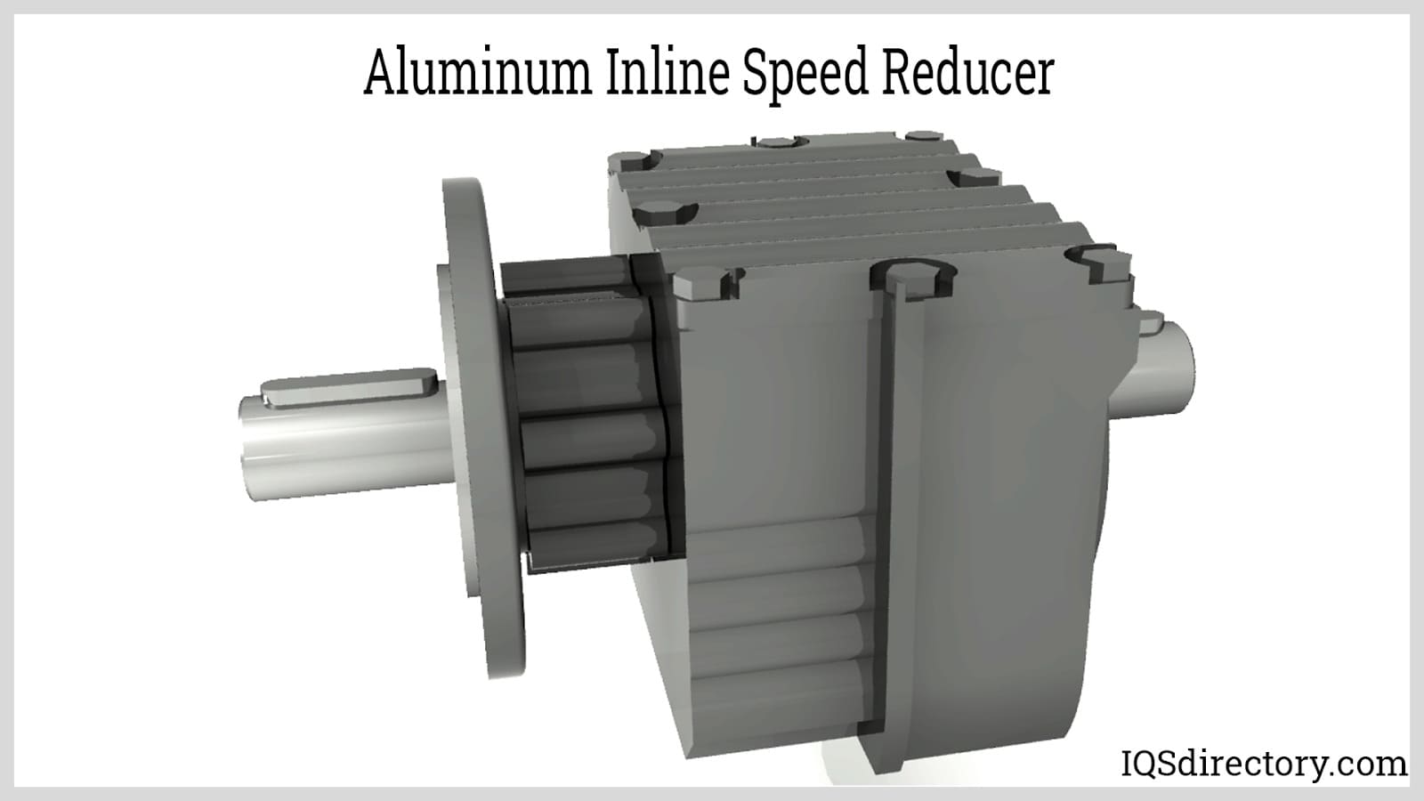 Speed reducers are gear train between the motor and the machinery used to slow down the transmission.
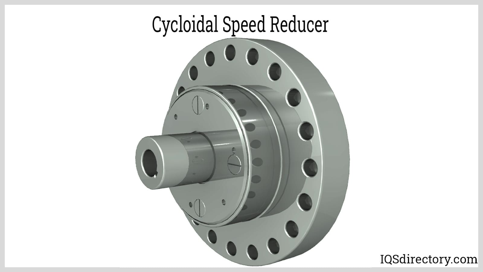 A cycloidal speed reducer, a device that reduces the speed of the input shaft which offers high ratios in a small package with little backlash.
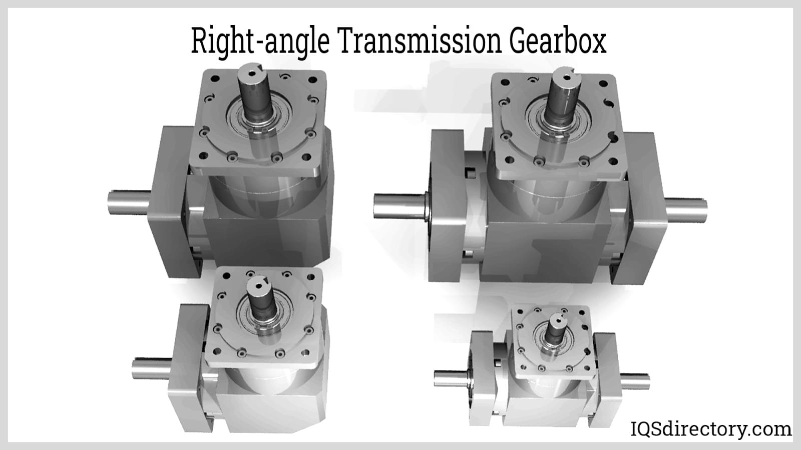 Right-angle gear drives are power transmission systems which use gears that transfers shaft power at a 90° angle.
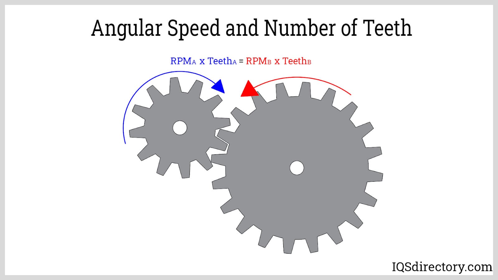 Gear drives can increase or decrease the speed of the driven shaft relative to the driver by using gears with different pitch diameters or numbers of teeth.
 Worm gear drives have two main components: the screw and the wheel, rotating the screw by 360° turning the wheel by the number of worm threads.
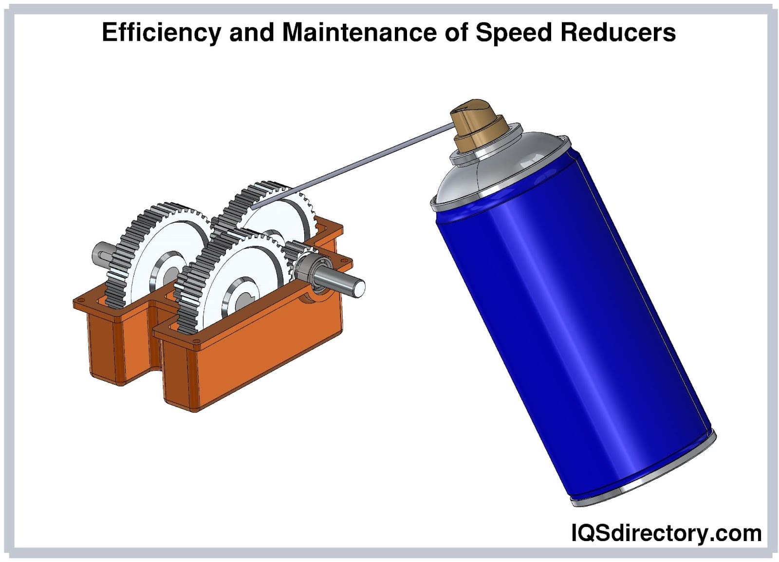 Regular maintenance improves efficiency of the speed reducers.
Speed Reducer Types
The term "speed reducer" encompasses a broad range of mechanical devices, including gear motors, gearboxes, gear drives, and gear reducers. The terminology used to describe these components often overlaps, making classification somewhat ambiguous. However, speed reducers can generally be categorized based on their mounting methods and design variations.
Primary Types of Speed Reducers
Inline Gear Reducer
Also referred to as an inline speed reducer, this type features an input shaft that aligns with the output shaft. It is integrated within a system alongside other components to reduce incoming speed and power, ensuring downstream parts can efficiently handle the load. Various types of gearing—such as planetary gears, cycloidal gear systems, helical gears, and spur gears—are commonly used in inline gear reducers.
Parallel Gearbox
Known as a parallel gear shaft speed reducer, this configuration includes both input and output shafts. While it functions similarly to inline gear reducers and offers increased flexibility, it is generally more expensive due to its design and performance advantages.
Right Angle Gear Box
This design positions the input shaft at a right angle to the output shaft, using either worm gearing or bevel gearing to achieve the necessary speed reduction. Some variations incorporate hybrid drives for enhanced efficiency. Among these designs, worm gear systems offer a cost-effective solution but tend to lose efficiency at higher reduction ratios, whereas bevel gear reducers maintain efficiency up to a reduction ratio of approximately 6:1. Due to its reliance on worm gearing, this type is often referred to as a worm gear reducer, worm gearbox, or worm speed reducer. Worm gear reducers are particularly well-suited for low-horsepower applications, offering high gear ratios, excellent shock tolerance, and a compact footprint.
Shaft Mounted Speed Reducer
This compact design eliminates the need for a separate foundation and coupling, as it mounts directly onto the drive shaft. This integration simplifies installation and reduces overall system complexity.
Additional Variations of Speed Reducers
Variable Speed Reducer
These devices regulate the rotational speed of an AC or DC electric motor. Depending on application requirements, they may be mechanical, electromechanical, hydraulic, or electronic. While some models work with both AC and DC motors, the majority are designed specifically for AC motors. Variable speed reducers enhance process control and energy efficiency by adjusting motor speed as needed.
Gear Reducer (Reducer Gear)
Designed to minimize power size and total machine footprint while handling heavy shock loads, this term is often used interchangeably with gear drives. Gear reducers play a key role in modifying output speed and torque in response to varying power input conditions.
Gearbox Speed Reducer
Also known as a speed reducer gearbox, this type lowers motor speed by reducing output speed and increasing torque. When mounted directly onto a motor rather than a shaft alone, it is referred to as a gear head.
Gear Motor Unit
A gear motor unit is formed when a speed reducer or gearbox is coupled with a standard C-frame motor. In some designs, the motor and reducer are linked using a coupler that connects the reducer’s input shaft to the motor shaft. Alternatively, a belt system may be used to transfer motor speed to the reducer.
Helical Gear Reducer
This type features teeth cut at an angle rather than parallel to the axis, resulting in smoother and quieter operation with improved load distribution.
Cyclo Reducer
A cyclo reducer slows input shaft speed by employing rolling elements and an off-center rotating disc to achieve the desired reduction ratio.
Planetary Gearbox
This design incorporates a sun gear, planet gears, and a ring gear, mimicking planetary motion to generate various reduction ratios. The planetary gear system, also known as epicyclic gearing, dates back to the second century when Ptolemy used it to model planetary movements.
Cycloidal Speed Reducer
Functioning similarly to the toothed gears found in mechanical clocks, these reducers operate based on epicycloid and hypocycloid movement rather than the standard involute gear profile.
Spur Gear
The simplest gear type, featuring radial teeth aligned parallel to the axis of motion, making them highly efficient for straightforward speed reduction applications.
Gear Reducer
These mechanisms alter speed, torque, or rotational direction through gear ratios. Gear drives enable variable output speeds from a constant-speed power source or enhance torque for a variable-speed power source.
Reduction Gears
Utilized to lower the speed or torque of a rotating input shaft, reduction gears use varying circumferences to achieve the desired reduction ratio. Gearboxes and other speed reducers depend on reduction gears to control output speed effectively.
Worm Gear Speed Reducers
As a subset of right-angle speed reducers, worm gear speed reducers are particularly useful in low-horsepower applications. They maintain high gear ratios, withstand shock loads, and provide a compact, space-efficient design.
Speed Reducer Applications
Speed reducers play a crucial role in controlling output speed across various mechanical systems. Gear reducers help minimize power size, reduce overall machine footprint, and withstand heavy shock loads, making them indispensable in many industries.
Industries that commonly rely on speed reducers include material handling, automation, automotive and transportation, aerospace, recreation, construction, food and beverage processing, oil and gas, and textiles. Their adaptability allows them to be integrated into an extensive range of applications, such as automation equipment, conveyors, compressors, printing presses, pumps, generators, and robotics. They are also widely utilized in metallurgy machinery, mining equipment, construction machinery, and other industrial machines that require precise speed control and torque management.
Speed Reducer Installation
When connecting a speed reducer to an input shaft, several key factors must be considered to ensure proper function and longevity. One of the primary concerns during installation is the radial load, also known as the overhang load. This force or torque acts on the shaft bearing due to its connection with components such as sprockets, pulleys, or belts.
Shaft bearings are engineered to accommodate radial loads, but if the applied force exceeds the design limits of the speed reducer, the entire gear arrangement can suffer structural failure. To prevent this, the radial load should be carefully calculated by dividing the transmitted torque by the radius of the connecting device, whether it be a pulley or a sprocket. Proper load management and installation techniques are essential to maintaining the efficiency and durability of the speed reducer system.
Standards and Specifications of Speed Reducers
When purchasing a speed reducer system, ensuring proper certification and compliance with industry standards is essential. The system should meet the guidelines set by recognized organizations, such as the International Standards Organization (ISO) and the American Gear Manufacturers Association (AGMA). These standards help guarantee performance, durability, and safety. To determine the specific requirements for your application and region, consult with your service provider to ensure compliance.
Choosing the Right Speed Reducer Manufacturer
Securing a high-quality speed reducer starts with selecting a reliable and experienced manufacturer. To simplify this process, we have compiled a comprehensive list of reputable speed reducer manufacturers and suppliers, conveniently located at the compressors. Our directory provides detailed company profiles, website links, locations, phone numbers, product videos, and technical information. You can also browse customer reviews and stay updated with product-specific news articles.
For deeper insights, request a fast quote or contact manufacturers directly. All of the companies listed are capable of designing, engineering, and manufacturing speed reducers tailored to your specific requirements. However, finding the right fit involves reaching out to multiple manufacturers—preferably three or four—to discuss your specifications, questions, and concerns. Compare their responses, paying close attention to price quotes, delivery schedules, lead times, and overall customer service. Choosing a manufacturer that prioritizes responsiveness and reliability will ensure a smooth partnership. Once you've made your decision, move forward with confidence and begin working with your new supplier.
Proper Care for Speed Reducers
Speed reducers handle significant rotational force, converting it into functional speed and torque. Throughout operation, they endure immense pressure, and without proper maintenance, they can deteriorate well before their rated lifespan. To ensure longevity and optimal performance, it is essential to follow key maintenance practices.
New Application
When introducing a speed reducer into a new application, avoid operating it under excessive loads. For the first two weeks, run the reducer with fresh oil and maintain standard load conditions as specified in the manufacturer’s handbook. This initial operation allows any fine particles trapped in the gear system to break loose and be easily removed. After the two-week period, drain the oil containing these particles and refill the unit with clean oil. To improve cost efficiency, consider filtering and reusing the oil rather than disposing of it immediately, as oil replacement contributes to higher operational expenses.
Preventive Maintenance
Over time, lubricants and oils within the speed reducer oxidize, forming sludge and acids that can degrade internal components. Preventive maintenance is crucial in mitigating this wear. Regularly lubricate the reducer with appropriate lubricants and follow a structured oil change schedule. While specific intervals vary depending on the design, a general best practice is to replace lubricants every 2,500 hours of operation. However, if the speed reducer is subjected to continuous heavy loads, more frequent oil changes may be necessary to prevent premature wear.
Reducer Lubrication
Inadequate lubrication is the leading cause of gearbox failure. Lubrication reduces friction between rolling and sliding gears while simultaneously dissipating heat by forming a protective film between components. Always use approved speed reducer lubricants, such as mineral-based or synthetic options like polyalkylene glycols and hydrocarbon polyalphaolefins. The lubricant's viscosity should align with the ambient operating temperature of the reducer. During operation, the lubricant must maintain an elasto-hydrodynamic (EHD) film between components to effectively dissipate heat and prevent damage.
Reducer Oiling
Maintaining the correct oil level is critical for extending the lifespan and ensuring the efficiency of a speed reducer. Consult the manufacturer’s specifications to determine the proper oil level, and always keep it within the recommended range. Operating with insufficient oil can lead to severe gearbox failure, while excessive oil can also cause issues by trapping excess air, reducing the system’s ability to regulate heat, and increasing the risk of overheating. For an accurate oil level reading, check the reducer only after it has been turned off and given sufficient time to cool.
Accessories for Speed Reducers
Various accessories can enhance the performance, functionality, and longevity of speed reducers. Some key options to consider include shift levers for precise control, paddle shifts for efficient gear changes, and gear position displays for real-time monitoring. Additional components such as oil pumps and oil coolers help regulate temperature and maintain lubrication, while slip yokes ensure smooth torque transmission. Bell housings provide structural support and protection, ensuring compatibility with different drive systems. Selecting the right accessories can optimize performance and extend the lifespan of your speed reducer.
Speed Reducer Terms
-
Actuator
A device that generates automatic motion by converting different forms of energy into either rotary or linear mechanical energy.
Axial Movement
Also known as "endplay," this refers to the movement of the end of a motor or gear shaft, typically measured in thousandths of an inch.
Backlash
A condition where the output shaft of a speed reducer moves while the input shaft remains stationary, often resulting in unintended play within the system.
Cam
A rotating disk designed to transform circular motion into linear motion, commonly used in mechanical systems requiring precise movement control.
Efficiency
A percentage-based measurement of a speed reducer’s ability to effectively reduce speed while maintaining power transmission. Efficiency is determined by comparing power input to power output.
Endshield
A component of a motor that houses the bearing supporting the rotor while also serving as a protective guard for the motor’s internal parts. It is sometimes referred to as the endbell, endplate, or end bracket.
Gear Ratio
A numerical representation of the relationship between the input speed of a gearmotor and the output speed of the gear head in a speed reducer.
Horsepower
A unit of work measurement equal to 33,000 foot-pounds per minute, 550 foot-pounds per second, or 746 watts.
Hysteresis
The difference in the output response of a mechanical system when subjected to a repeated input, influenced by factors such as bi-directional repeatability and mechanical lag.
Input Horsepower
The total power output of a motor that a speed reducer is capable of handling at its input shaft.
Lost Motion
Motion that is not effectively transmitted within a system due to mechanical hysteresis, backlash, or torsional stiffness in rotational components.
Mechanical Rating
The maximum amount of power a speed reducer can handle before experiencing overload or potential failure.
Mounting Position
The specific orientation in which a speed reducer’s input and output shafts are positioned within a system, affecting its overall performance and integration.
Output Horsepower
The amount of power delivered from the output shaft of a speed reducer, which is directly influenced by the efficiency of the system.
Output Shaft
The part of the speed reducer that connects to the driven equipment, responsible for transmitting power and torque to facilitate mechanical operation.
Thermal Rating
A measurement indicating the continuous power transmission capacity of a speed reducer, factoring in heat generation and dissipation to ensure operational reliability.

